![]()
![]()
Graphics Getting Started Application on SAM9X60 Curiosity Development Board
Download
Description
This graphics application demonstrates how to display the Microchip Graphics Quick Start project template to the Maxtouch 5-inch display on the SAM9X60 Curiosity Development board.
Key Highlights of SAM9X60 Curiosity Development Board:
- LCD Interface.
- External Non-Volatile Memories like NAND, SD, and MicroSD card interfaces.
- Additional sensors can be interfaced using “click boards” through an on-board mikroBUS connector.
- Two mechanical programmable buttons.
- One User Input Switch and one RGB LED.
- UART, USB and CAN Interfaces.
- Raspberry pi connectors.
Modules/Technology Used:
- Peripheral Modules
- Flexcom
- LCDC Interface
- TC0 (TWI/I2C)
- MAXTOUCH Controller interface
Hardware Used:
- SAM9X60 Curiosity development board
- High-Performance WVGA LCD Display Module with maXTouch ® Technology
- Micro SD Card
Software/Tools Used:
This project has been verified to work with the following versions of software tools:
Refer Project Manifest present in harmony-manifest-success.yml under the project folder firmware/src/config/lcdc_rgba8888_mxt_9x60_wvga to know the MPLAB® X IDE, MCC Plugin, libraries version
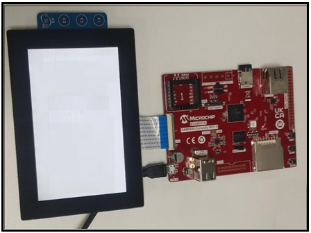
Hardware Setup :
- Connect the ribbon cable from the display to the J13 connector of the SAM9X60 Curiosity Development Board.
- Power up the board by connecting the USB cable to the USB port J1 on the SAM9X60 curiosity development board.
- Connect external debugger to J12.
Developing a graphics getting started demo
Details
-
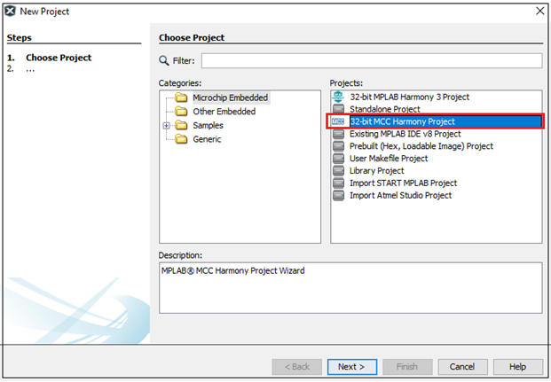
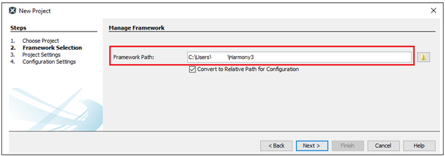
Launch MPLAB® X IDE- From the main menu, click on File, then New Project. Under “Projects” choose
32-bit MCC Harmony Project, click Next- ForFramework Pathchoose the location on your PC where you want to download the Harmony 3 framework- Click Next.
-
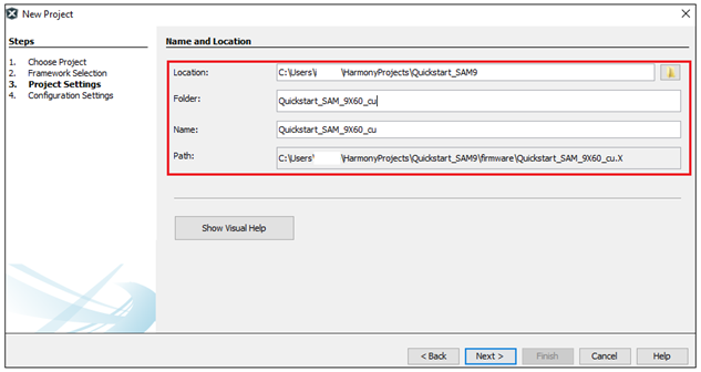
Enter
Location,FolderandNameof the project. Click Next.
-
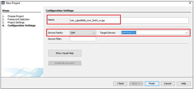
In the
Configuration Settingswindow, forNameenterlcdc_rgba8888_mxt_9x60_wvga, forDevice FamilyselectSAM, forTarget DeviceselectSAM9X60D1G. Click Finish.
This creates an empty project and set this project asmain projectif there are other projects open in the project explorer window.
-
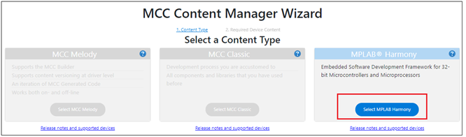
From main menu, click on
Tools->Embedded->MPLAB® Code Configuratoror click MCC button in the MPLAB® X IDE tool bar. It will launch Content manger Wizard. Then select MPLAB® Harmony.
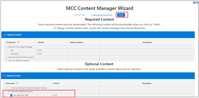
-
In addition to the required packages, download the optional packages gfx_sam9x60, bsp, csp, core, gfx, dev_packs and then click Finish. Content download will take some time. Please wait till all the contents are downloaded.
-
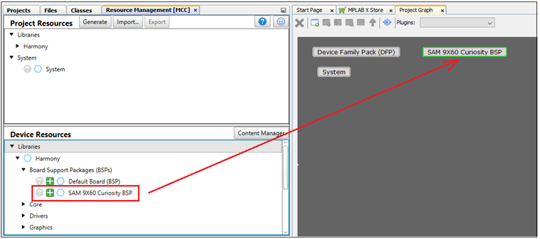
Now project graph will be displayed. From device resource add
Board Support PackagesforSAM9X60 Curiosity Kit BSPtoProject Graph.
-
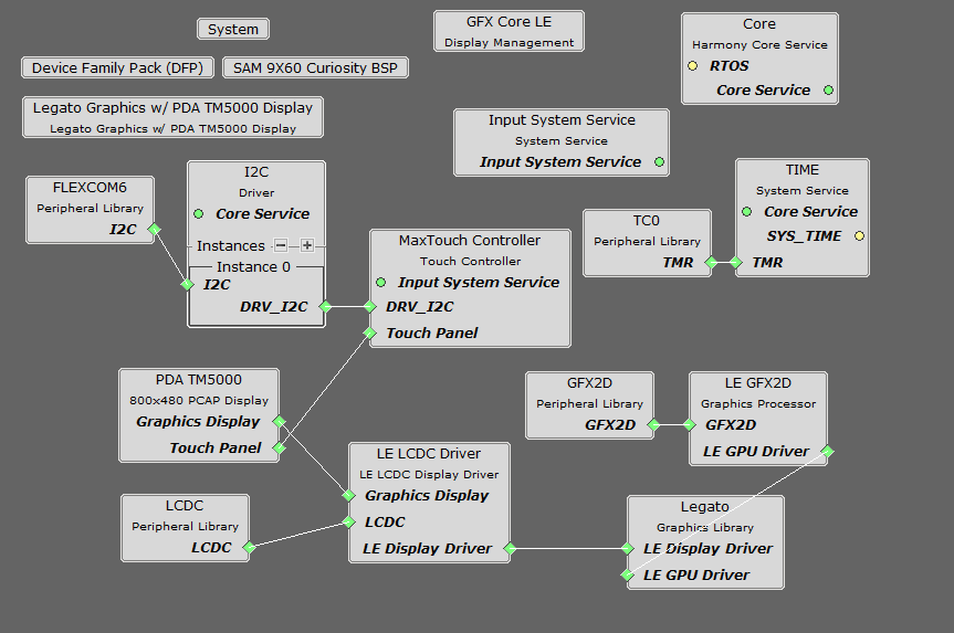
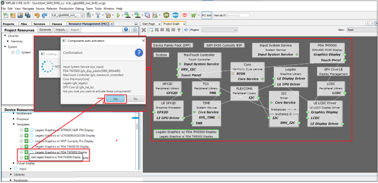
From device resource add Graphics -> Templates ->
Legato Graphics w/PDA TM5000 DisplaytoProject Graph. You will be prompted to allow auto-connection and auto-activation of several components- Click on Yes for all of them except “FreeRTOS”.
-
Choosing the
Legato Graphics w/PDA TM5000 Displaytemplate automatically populates rest of the project components. This can be seen in the way the project graph is setup and connected. -
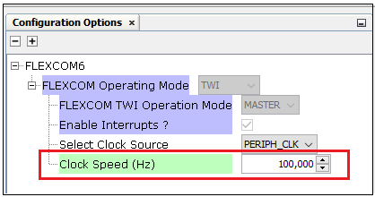
In the project graph, click on
Flexcom6. In theConfiguration Optionswindow, select clock speed as 100,000 (100KHz).
-
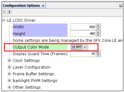
In the project graph, click on
LE LCDC Driver. In theConfiguration Optionswindow, select output color mode as 18BPP.
-
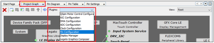
From the project graph window, plugins menu select
Pin Configuration.
-
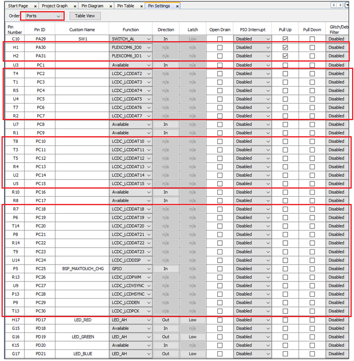
You can see that PA30 and PA31 are set to FLEXCOM6. Enable pullups for those pins. Ensure all the pins are configured as below:
-
Now Save all. Then click generate code. This will generate code for all the peripherals that have been added in the project graph.
-
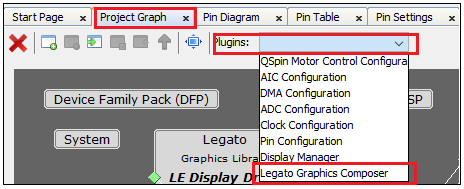
Now let us use Microchip Graphics Composer(MGC) to design the graphics to be displayed on the LCD screen and generate the legato library. From the Project graph -> plugin, launch Legato Graphics Composer. (From next software update, this plugin will be renamed to Microchip Graphics Composer)
-
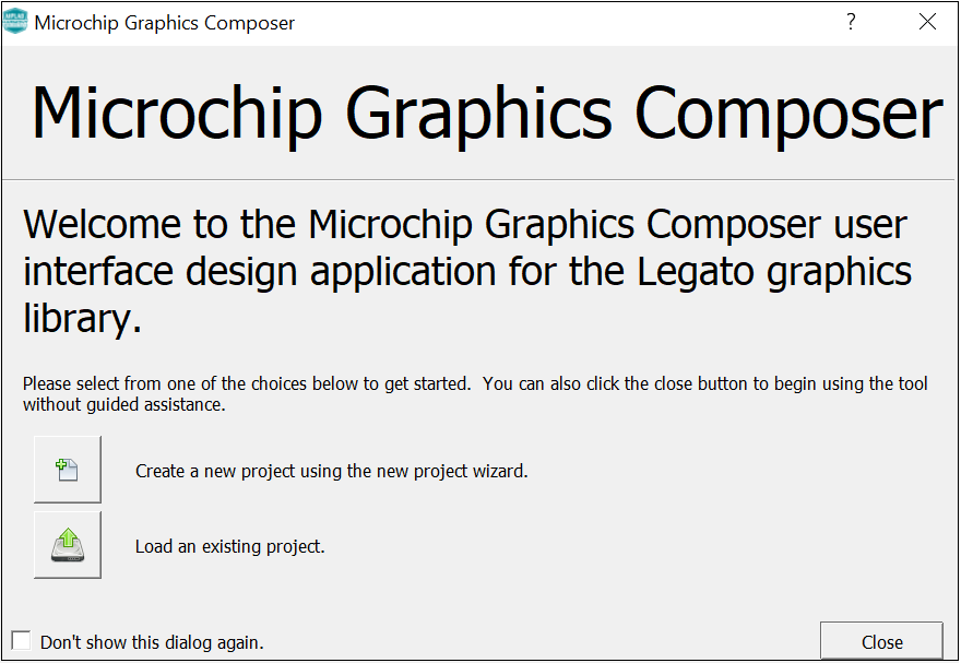
From the window that pops-up, click on
Create a new projectusing the new project wizard.
-
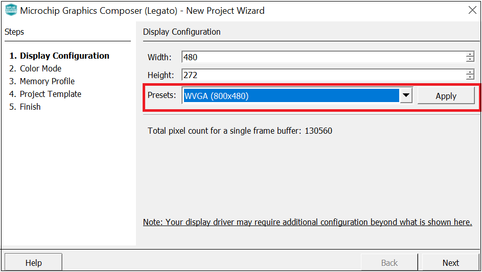
In the
Display Configurationwindow, chooseWVGA (800x480)forPresetsand click on Apply. You will see that the Width and Height are updated. Click Next.
-
For
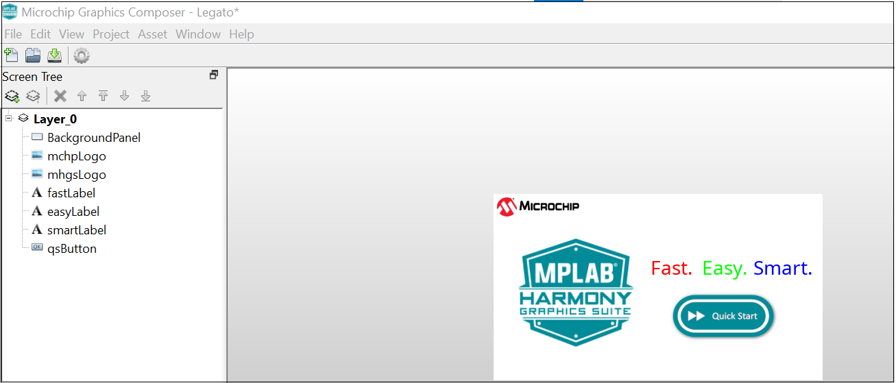
Color Mode-> select RGBA_8888. Click Next. ForMemory Profile-> selectMPU. Click Next. In theProject Templatewindow, select theStart with a basic quickstart project templatecheckbox. Click Next. Click Finish -
You will see the following screen generated by the composer.
-
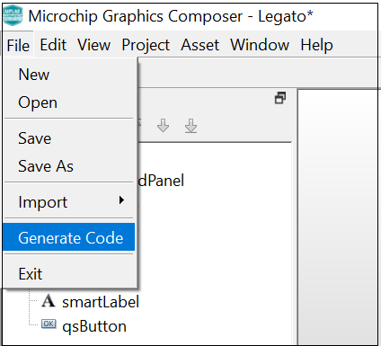
After the graphics display is composed, you can generate the design files by clicking the
Generate Codefrom the File option in the main menu .
-
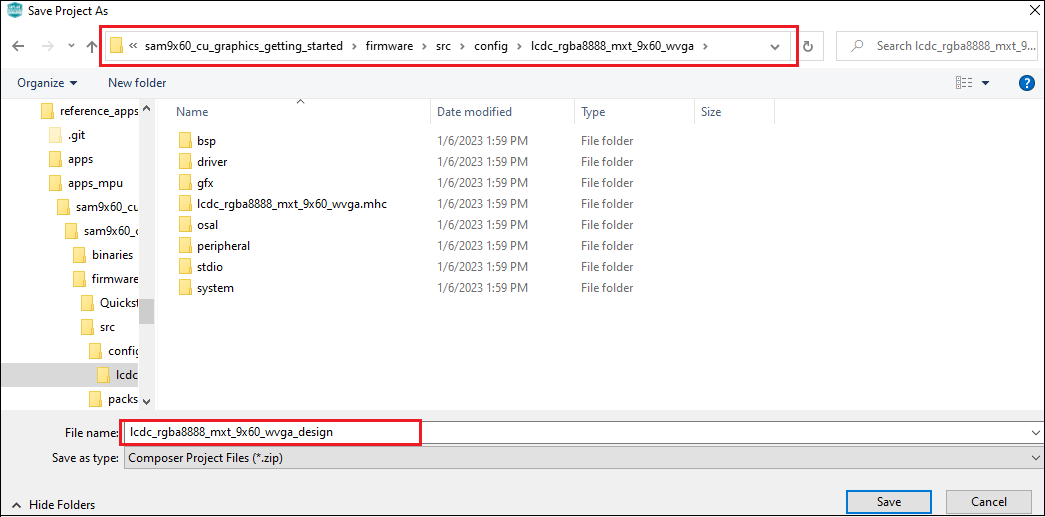
You can save the design files by clicking on File from the main menu and selecting
Save As. Provide a filename with_design and save it in the ( That way the next time MGC is launched, the design file is automatically opened) and click Save.
-
You can now exit Microchip Graphics Composer by clicking on Exit from File option in the main menu.
-
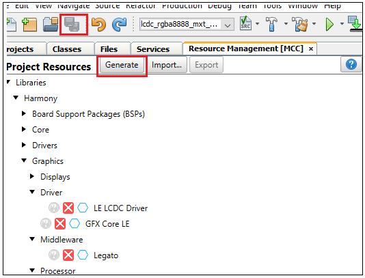
From MCC, click on Generate Code. This will generate code for the quickstart template designed using Microchip Graphics Composer.
-
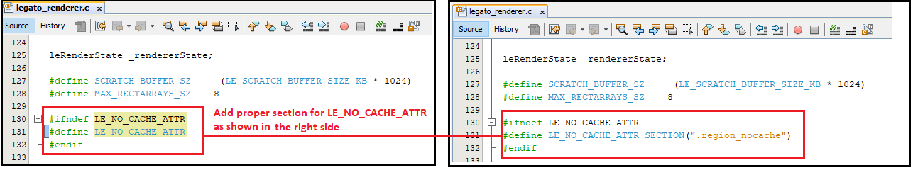
Lastly change the following code. In Legato -> renderer -> legato_renderer.c, add proper section for no cache attribute as shown below:
The.region_nocachememory location is defined in the linker file and lets the linker know which memory region is to be used for scratch buffers.
-
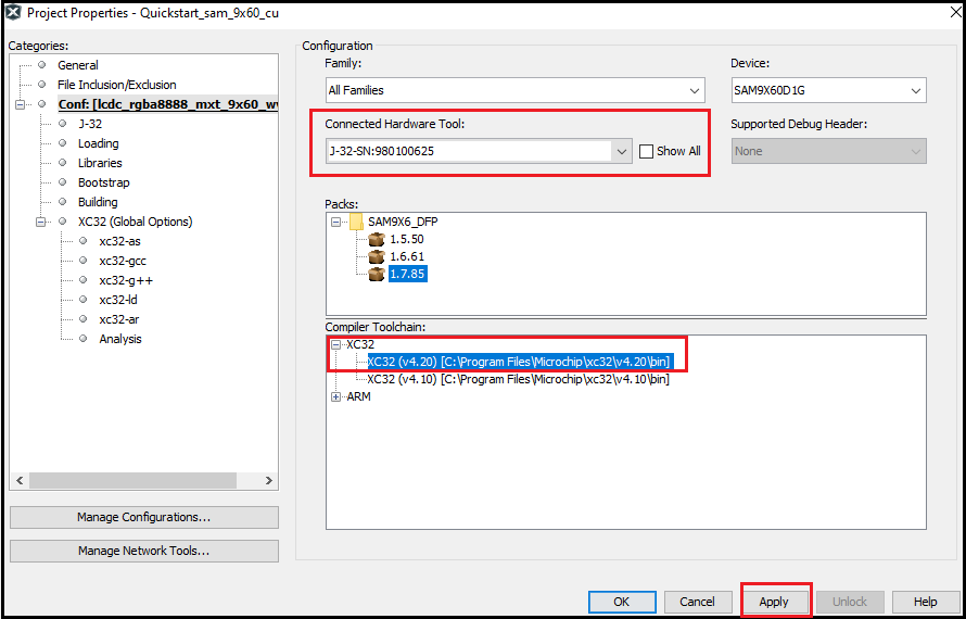
Now right click on the project and click
Properties. ForConnected Hardware Tool-> select connected hardware debugger used, forCompiler Toolchain-> select XC32 and click Apply.
-
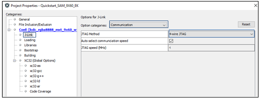
From J-32 ,
Option categorieschooseCommunicationand forJTAG Method, select4-wire JTAG.
-
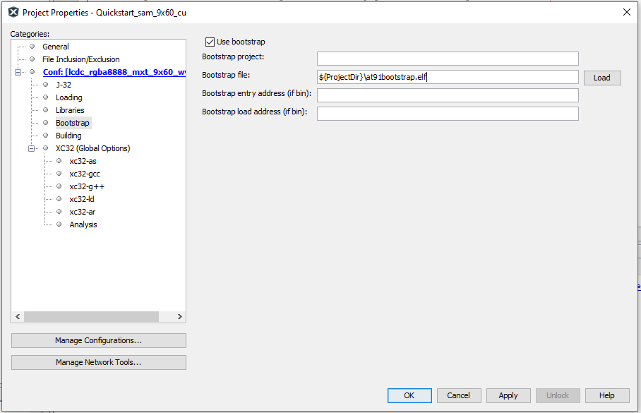
Select Bootstrap for Categories and select the
Use Bootstrapcheckbox. Forbootstrap file-> select the at91bootstrap elf file from here- Click on Apply and OK.
-
Clean and build the project. You should see a message on the output console that the project was successfully built. This completes the development of the basic graphics quickstart getting started application.
Debugging Application Project on MPLAB® X IDE:
- Open the project (sam9x60_cu_graphics_getting_started/firmware/sam9x60_cu.X) in MPLAB® X IDE.
- Ensure “SAM9X60D1G” is selected as hardware tool to program/debug the application.
- Build the code and Debug the code by clicking on the “Debug” button in MPLAB® X IDE tool bar.
- Run the application by clicking “run” button in MPLAB® X IDE tool bar.
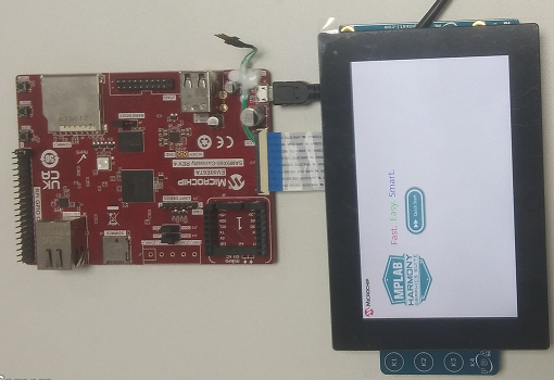
- Now the below legato quickstart template application will get displayed on the LCD connected with SAM9X60 Curiosity development board.
Running the pre-built harmony application from SD Card:
The pre-built application bin file can be programmed by following the below steps
Steps to program the bin file on SD card
- Take a micro-SD Card formatted with FAT32 file system.
- Copy the boot.bin and harmony.bin files from this location to the micro-SD card using your PC.
- Insert the SD card to J3 on the SAM9X60 Curiosity development board.
Steps to run the bin file from SD card
- Press the reset button.
- It will display the below graphics getting started demo -a legato quickstart template application on the display connected with SAM9X60 Curiosity development board.
Comments:
- This application demo builds and works out of box by following the instructions above in “Running the Demo” section- If you need to enhance/customize this application demo, you need to use the MPLAB® Harmony v3 Software framework- Refer links below to setup and build your applications using MPLAB® Harmony.
- How to Setup MPLAB® Harmony v3 Software Development Framework
- How to Build an Application by Adding a New PLIB, Driver, or Middleware to an Existing MPLAB® Harmony v3 Project
- Click Here for more graphics demos
- MPLAB® Harmony v3 is also configurable through MPLAB® Code Configurator (MCC)- Refer to the below links for specific instructions to use MPLAB® Harmony v3 with MCC.
- Getting Started with MPLAB® Harmony v3 Using MPLAB® Code Configurator
- MPLAB® Code Configurator Content Manager for MPLAB® Harmony v3 Projects
Revision:
- v1.6.0 - Released demo application