![]()
![]()
RFID Click example on SAM E51 Curiosity Nano Evaluation Kit
Download
Description:
This example demonstrates the reading of RFID tag information and displays it on a serial terminal on SAM E51 Curiosity Nano Evaluation Kit using RFID Click board.
Modules/Technology Used:
- Peripheral Modules
- EIC
- SYSTICK
- GPIO
- SERCOM (SPI)
Hardware Used:
- SAM E51 Curiosity Nano Evaluation Kit
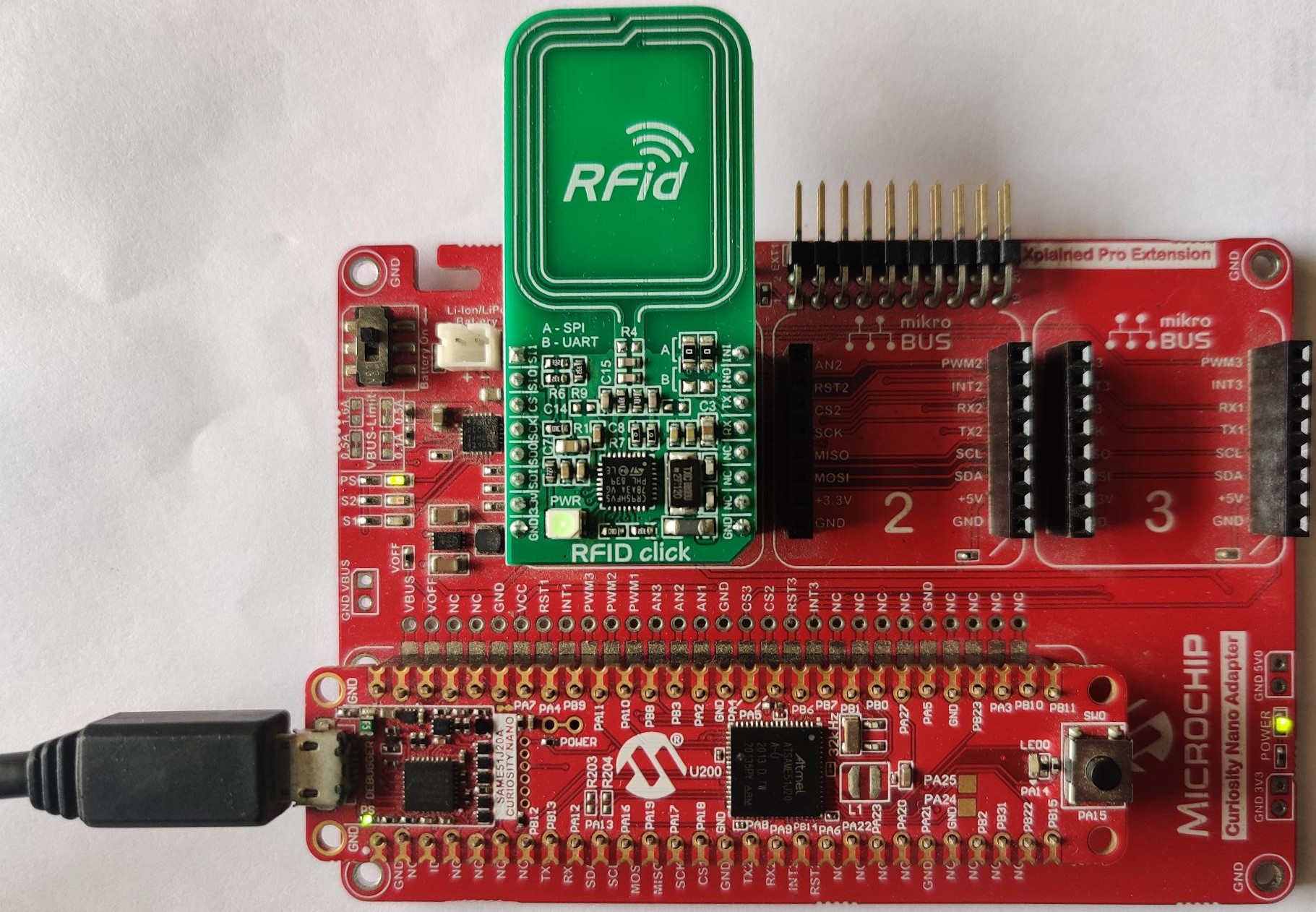
- Curiosity Nano Base for Click Boards
- MikroElektronika RFID Click
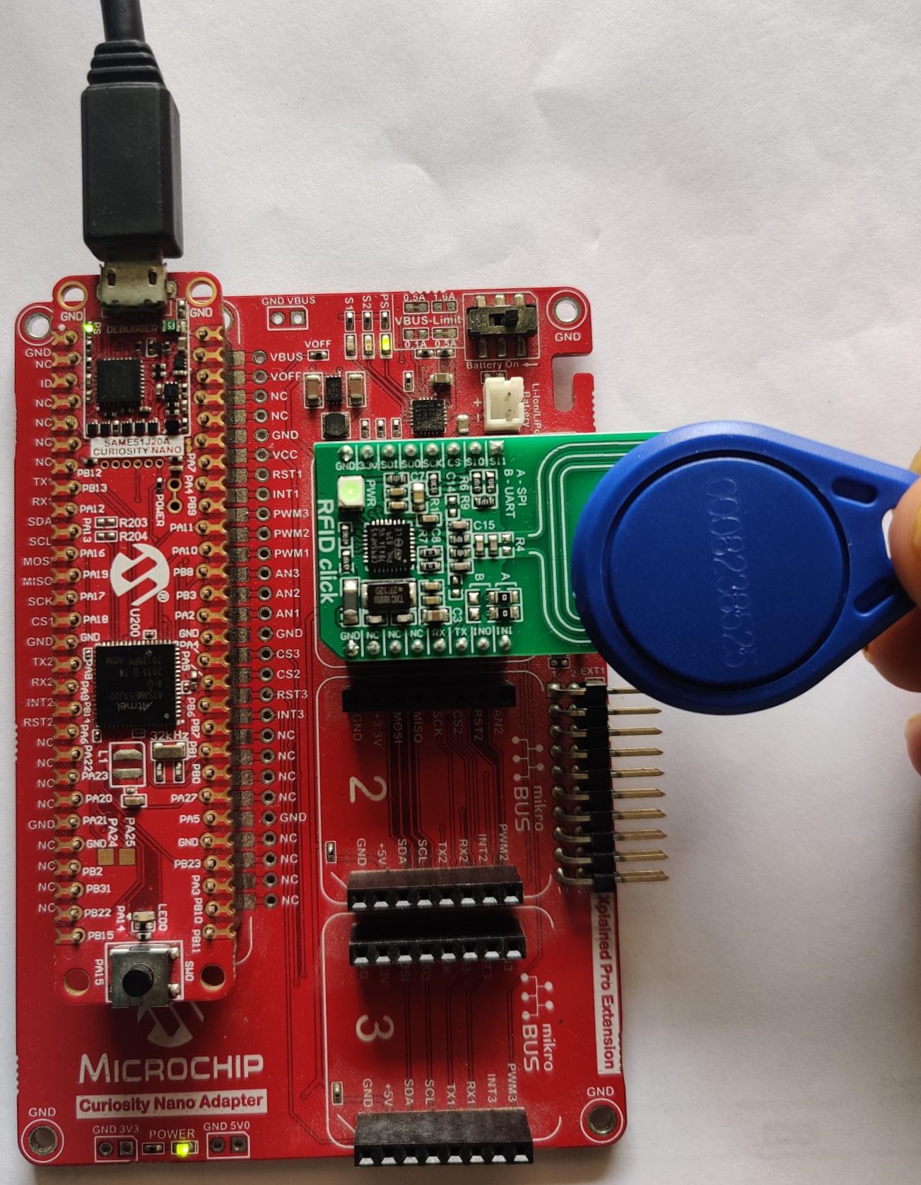
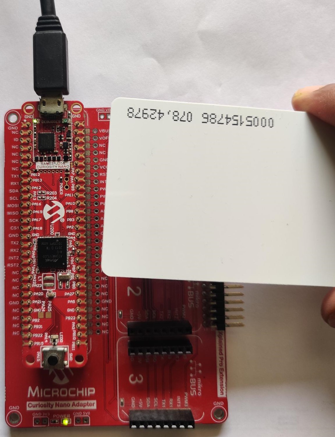
- RFID 13.56MHz Card or 13.56MHz RFID IC Key Tag
Software/Tools Used:
This project has been verified to work with the following versions of software tools:
Refer Project Manifest present in harmony-manifest-success.yml under the project folder firmware/src/config/sam_e51_cnano
- Refer the Release Notes to know the MPLAB X IDE and MCC Plugin version. Alternatively, Click Here.
- Any Serial Terminal application like Tera Term terminal application.
Because Microchip regularly update tools, occasionally issue(s) could be discovered while using the newer versions of the tools. If the project doesn’t seem to work and version incompatibility is suspected, It is recommended to double-check and use the same versions that the project was tested with. To download original version of MPLAB Harmony v3 packages, refer to document How to Use the MPLAB Harmony v3 Project Manifest Feature
Setup:
-
Connect the SAM E51 Curiosity Nano Evaluation Kit to the Host PC as a USB Device through a Type-A male to micro-B USB cable connected to Micro-B USB (Debug USB) port
Programming hex file:
The pre-built hex file can be programmed by following the below steps.
Steps to program the hex file
- Open MPLAB X IDE
- Close all existing projects in IDE, if any project is opened.
- Go to File -> Import -> Hex/ELF File
- In the “Import Image File” window, Step 1 - Create Prebuilt Project, Click the “Browse” button to select the prebuilt hex file.
- Select Device has “ATSAME51J20A”
- Ensure the proper tool is selected under “Hardware Tool”
- Click on Next button
- In the “Import Image File” window, Step 2 - Select Project Name and Folder, select appropriate project name and folder
- Click on Finish button
- In MPLAB X IDE, click on “Make and Program Device” Button. The device gets programmed in sometime
- Follow the steps in “Running the Demo” section below
Programming/Debugging Application Project:
- Open the project (sam_e51_cnano/same51n_mikroe_click/rfid/firmware/sam_e51_cnano.X) in MPLAB X IDE
- Ensure “SAM E51 Curiosity Nano” is selected as hardware tool to program/debug the application
- Build the code and program the device by clicking on the “Make and Program Device” button in MPLAB X IDE tool bar
- Follow the steps in “Running the Demo” section below
Running the Demo:
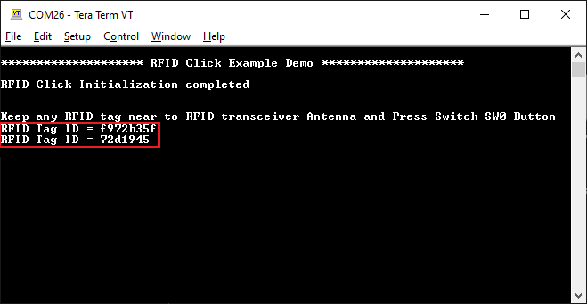
- Open the Tera Term terminal application on your PC (from the Windows® Start menu by pressing the Start button)
- Set the baud rate to 115200
-
Keep any 13.56 MHz RFID tags near to RFID as shown here.
- Press the switch SW0 on the SAM E51 Curiosity Nano Evaluation Kit to start read the RFID tag information if any tag presents nearby RFID field.
- For every switch press, the SAM E51 Curiosity Nano Evaluation Kit prints the read the RFID tag information if any tag presents nearby RFID field..
Instructions to add RFID functionality to your application:
You could use this demonstration as an example to add RFID functionality to your MPLAB Harmony v3 based application. Follow the below steps.
- If you haven’t downloaded the RFID demo yet Click Here to download, otherwise go to next step
- Unzip the downloaded .zip file
- From the unzipped folder rfid/firmware/src, copy the folder click_routines to the folder firmware/src under your MPLAB Harmony v3 application project
- Open MPLAB X IDE
- Open your application project
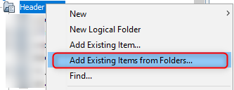
- In the project explorer, Right click on folder Header Files
and add a sub folder click_routines by selecting “Add Existing Items from Folders…”
-
Click on “Add Folder…” button

-
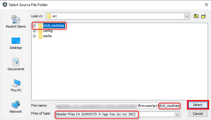
Select the “click_routines” folder and select “Files of Types” as Header Files
-
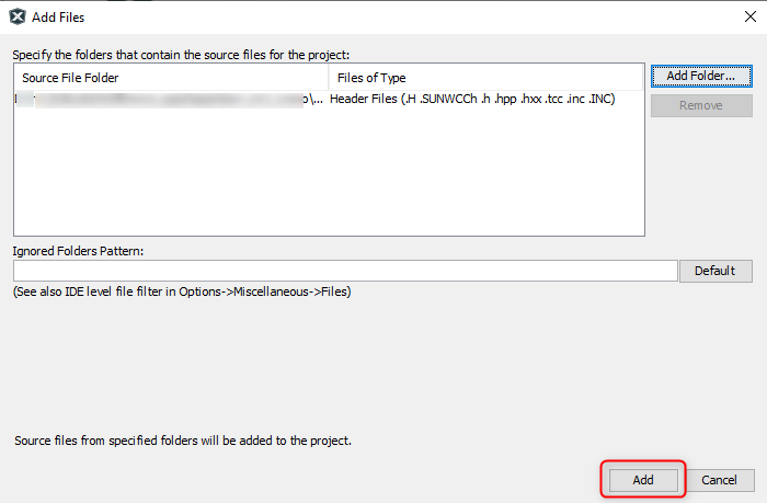
Click on “Add” button to add the selected folder
-
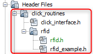
The RFID click example header files gets added to your project
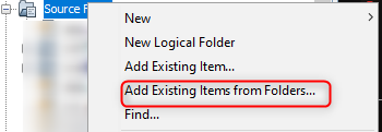
- In the project explorer, Right click on folder Source Files
and add a sub folder click_routines by selecting “Add Existing Items from Folders…”
-
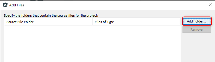
Click on “Add Folder…” button
-
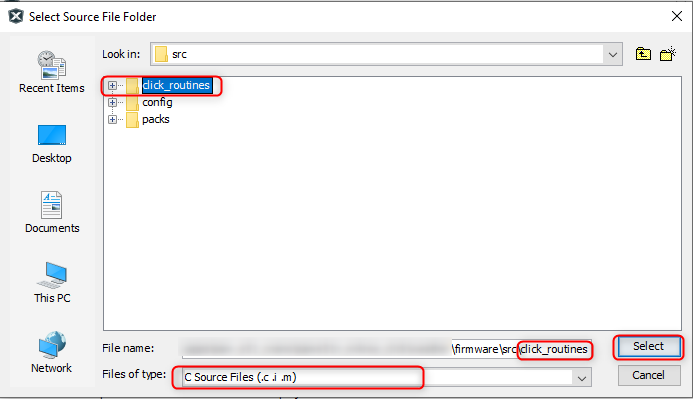
Select the “click_routines” folder and select “Files of Types” as Source Files
-
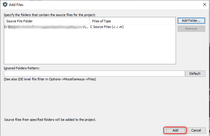
Click on “Add” button to add the selected folder
-
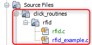
The RFID click example source files gets added to your project
-
The RFID click example uses the SPI and Timer peripherals. The configuration of these peripherals for your application depends on the 32-bit MCU and development board you are using.
- Configure SPI: - Add the SPI peripheral block to the MCC project graph
- Configure SPI Pins using MCC Pin configuration Window
The SPI configuration depends on - 32-bit MCU - 32-bit MCU development board - The socket on which you have mounted the RFID click board
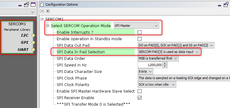
Example: The RFID click example on SAM E51 Curiosity Nano Evaluation Kit uses mikroBUS socket #1 on the Curiosity Nano Base for Click boards to mount the RFID click board. The SPI lines from MCU coming to this socket are from the SERCOM1 peripheral on the MCU.
MCC Project Graph - SPI configuration
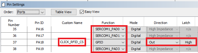
MCC Pin Configurator - SPI pin configuration
- Configure SPI Pins using MCC Pin configuration Window
- Configure Timer:
- Configure Timer peripheral block in the MCC project graph
The Timer configuration depends on - 32-bit MCU
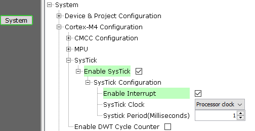
Example: The RFID click example on SAM E51 Curiosity Nano Evaluation Kit uses SysTick timer module on the MCU to implement the time requirement of RFID click routines.
MCC Project Graph - SysTick configuration
- Configure Timer peripheral block in the MCC project graph
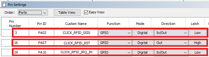
- Configure PORT Pins:
- The RFID click needs three additional pins for configuration and data exchange. These parent
- Interrupt input pin
- Select serial communication interface pin
- Reset pin
- Configure PORT pins needed by RFID click in the MCC Pin Configurator
The PORT pin configuration depends on- 32-bit MCU
- 32-bit MCU development board
- The socket on which you have mounted the RFID click board
Example: The PORT pin configuration for the RFID click example on SAM E51 Curiosity Nano Evaluation Kit is below.
MCC Pin Configurator - PORT pin configuration
- The RFID click needs three additional pins for configuration and data exchange. These parent
- Map Generic Macros:
- After generating the project, following the above configuration, map the generic macros used in the click routines to the Harmony PLIB APIs of the 32-bit MCU your project is running on
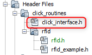
-
The generic macros should be mapped in the header file click_interface.h
 Example: The RFID click routines for the example on SAM E51 Curiosity Nano Evaluation Kit uses the following Harmony PLIB APIs
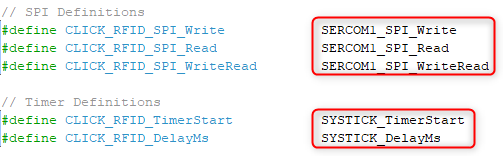
- Configure SPI: - Add the SPI peripheral block to the MCC project graph
-
The click_routines folder contain an example C source file rfid_example.c. You could use rfid_example.c as a reference to add RFID functionality in your application.
Comments:
- Reference Training Module:
- This application demo builds and works out of box by following the instructions above in “Running the Demo” section. If you need to enhance/customize this application demo, you need to use the MPLAB Harmony v3 Software framework. Refer links below to setup and build your applications using MPLAB Harmony.
- How to Setup MPLAB Harmony v3 Software Development Framework
- How to Build an Application by Adding a New PLIB, Driver, or Middleware to an Existing MPLAB Harmony v3 Project
- MPLAB Harmony v3 is also configurable through MPLAB Code Configurator (MCC). Refer to the below links for specific instructions to use MPLAB Harmony v3 with MCC.
Revision:
- v1.6.0 - Regenerated and Tested the application.
- v1.5.0 - Removed MHC support, regenerated and tested application.
- v1.4.0 - Added MCC support, regenerated and tested application.
- v1.3.0 - Released demo application