![]()
![]()
Getting Started Application on PIC32MK General Purpose (GP) Development Kit
Download
Description
The application reads the current room temperature from the temperature sensor on the MikroElectronika Weather click board. The temperature reading is displayed on a serial console periodically every 500 milliseconds. The periodicity of the temperature values displayed on the serial console is changed to one second, two seconds, four seconds, and back to 500 milliseconds every time you press the switch S1 on the PIC32MK GP Development Kit. Also, an LED (LED1) is toggled every time the temperature is displayed on the serial console.
Modules/Technology Used:
- Peripheral Modules
- SPI
- Timer
- Core Timer
- GPIO
- UART
- DMA
Hardware Used:
Software/Tools Used:
This project has been verified to work with the following versions of software tools:
Refer Project Manifest present in harmony-manifest-success.yml under the project folder firmware/src/config/pic32mk_gp_db
- Refer the Release Notes to know the MPLAB X IDE and MCC Plugin version. Alternatively, Click Here.
- Any Serial Terminal application like Tera Term terminal application.
Because Microchip regularly update tools, occasionally issue(s) could be discovered while using the newer versions of the tools. If the project doesn’t seem to work and version incompatibility is suspected, It is recommended to double-check and use the same versions that the project was tested with. To download original version of MPLAB Harmony v3 packages, refer to document How to Use the MPLAB Harmony v3 Project Manifest Feature
Setup:
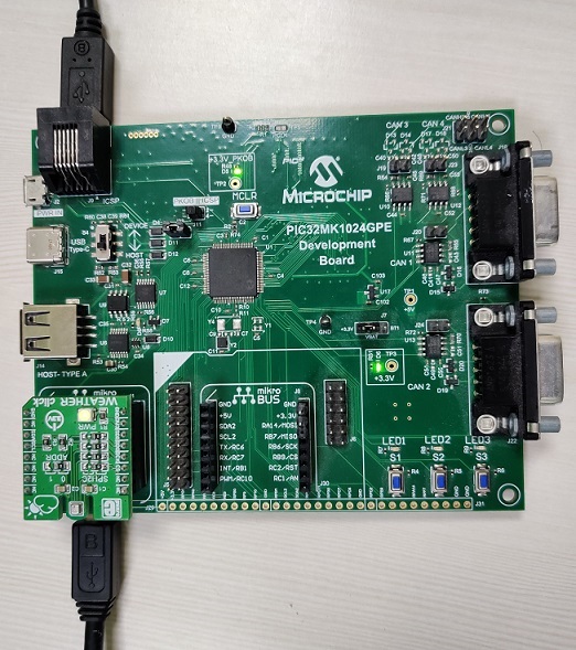
- Connect the Type-A male to Micro-B USB cable to the Micro-B Serial USB port (J25) on the PIC32MK GP Development Kit for logs
- Connect the Type-A male to Micro-B USB cable to Micro-B DEBUG USB port (J12) to power and debug the PIC32MK GP Development Kit
- Connect the MikroElectronika Weather click board on the mikroBUS interface J29. Ensure the following hardware modification before connecting the Weather click board
Hardware Modification:
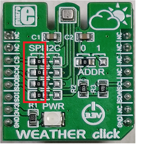
- The MikroElectronika Weather click board supports both I²C and SPI protocols to communicate with the BME280 temperature sensor.
It provides jumpers (resistors) to choose a communication interface between I²C and SPI. By default, I²C is selected as the communication interface. The PIC32MK1024GPE100 device does not have an I²C peripheral module; therefore, SPI is chosen as the communication interface to communicate with the temperature sensor.
The hardware modification to be done on the MikroElectronika Weather click board is shown in the figure below
Programming hex file:
The pre-built hex file can be programmed by following the below steps
Steps to program the hex file
- Open MPLAB X IDE
- Close all existing projects in IDE, if any project is opened.
- Go to File -> Import -> Hex/ELF File
- In the “Import Image File” window, Step 1 - Create Prebuilt Project, click the “Browse” button to select the prebuilt hex file.
- Select Device has “PIC32MK1024GPE100”
- Ensure the proper tool is selected under “Hardware Tool”
- Click on “Next” button
- In the “Import Image File” window, Step 2 - Select Project Name and Folder, select appropriate project name and folder
- Click on “Finish” button
- In MPLAB X IDE, click on “Make and Program Device” Button. The device gets programmed in sometime.
- Follow the steps in “Running the Demo” section below
Programming/Debugging Application Project:
- Open the project (pic32mk_getting_started\firmware\pic32mk_gp_db.X) in MPLAB X IDE
- Ensure “Starter Kits (PKOB)” is selected as hardware tool to program/debug the application
- Build the code and program the device by clicking on the “Make and Program Device” button in MPLAB X IDE tool bar
- Follow the steps in “Running the Demo” section below
Running the Demo:
- Open the Tera Term terminal application on your PC (from the Windows® Start menu by pressing the Start button)
- Change the baud rate to 115200
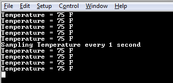
- You should see the temperature values (in °F) being displayed on the terminal every 500 milliseconds, as shown below
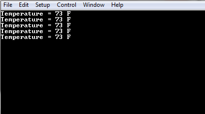
- Also, notice LED1 blinking at a 500 millisecond rate
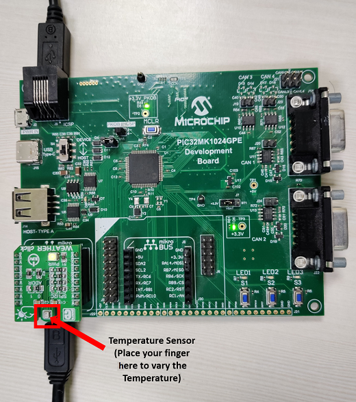
- You may vary the temperature by placing your finger on the temperature sensor (for a few seconds)
- Press the S1 switch on the PIC32MK General Purpose (GP) Development Kit to change the default sampling rate to one second
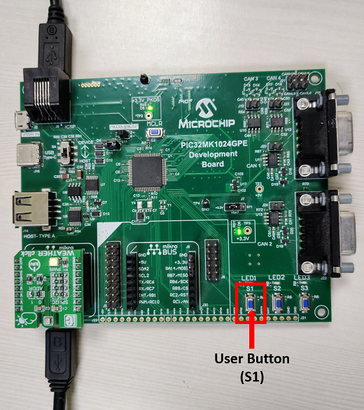
-
Every subsequent press of switch S1 on the PIC32MK General Purpose (GP) Development Kit changes the default sampling rate to two seconds, four seconds, 500 milliseconds and back to one second in cyclic order as shown below
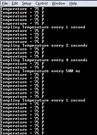
- While the temperature sampling rate changes on every switch S1 press, notice LED1 toggling at the same sampling rate
Comments:
- Reference Training Module: Getting Started with Harmony v3 Peripheral Libraries on PIC32MK GP MCUs
- This application demo builds and works out of box by following the instructions above in “Running the Demo” section. If you need to enhance/customize this application demo, you need to use the MPLAB Harmony v3 Software framework. Refer links below to setup and build your applications using MPLAB Harmony.
- How to Setup MPLAB Harmony v3 Software Development Framework
- How to Build an Application by Adding a New PLIB, Driver, or Middleware to an Existing MPLAB Harmony v3 Project
- MPLAB Harmony v3 is also configurable through MPLAB Code Configurator (MCC). Refer to the below links for specific instructions to use MPLAB Harmony v3 with MCC.
Revision:
- v1.6.0 - Regenerated and tested the application
- v1.5.0 - Removed MHC support, regenerated and tested application.
- v1.4.0 - Added MCC support, regenerated and tested application.
- v1.3.0 - Regenerated and tested application.
- v1.2.0 - Regenerated and tested application.
- v1.1.0 - Regenerated and tested application.
- v1.0.0 - Released demo application