![]()
![]()
Getting Started Application using Harmony v3 Drivers, System Services, Middleware and FreeRTOS on Curiosity PIC32MZ EF 2.0 Development Board
Download
Description
The application reads the current room temperature from the temperature sensor on the I/O1 Xplained Pro Extension Kit. The temperature reading is displayed on a serial console periodically every second. Further, the application writes the temperature readings to EEPROM and to a file in a USB thumb drive whenever the USB thumb drive is connected. Also, an LED LED1 is toggled every time the temperature is displayed on the serial console and an LED (LED2) is in ON state when a USB thumb drive is connected.
Modules/Technology Used:
- Peripheral Modules
- I2C
- Timer
- GPIO
- UART
- DMA
- Drivers
- USB High-Speed Driver
- USART Synchronous Drive
- I²C Synchronous Driver
- System Services
- File System Services
- Middleware
- USB Host
- Third Party Libraries
- FreeRTOS
Hardware Used:
Software/Tools Used:
This project has been verified to work with the following versions of software tools:
Refer Project Manifest present in harmony-manifest-success.yml under the project folder firmware/src/config/pic32mz_ef_curiosity_v2
- Refer the Release Notes to know the MPLAB X IDE and MCC Plugin version. Alternatively, Click Here.
- Any Serial Terminal application like Tera Term terminal application.
Because Microchip regularly update tools, occasionally issue(s) could be discovered while using the newer versions of the tools. If the project doesn’t seem to work and version incompatibility is suspected, It is recommended to double-check and use the same versions that the project was tested with. To download original version of MPLAB Harmony v3 packages, refer to document How to Use the MPLAB Harmony v3 Project Manifest Feature
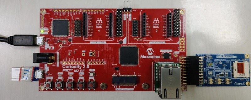
Setup:
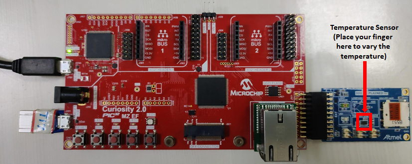
- Connect the Curiosity PIC32MZ EF 2.0 Development Board to the Host PC as a USB Device through a Type-A male to micro-B USB cable connected to Micro-B USB (Debug USB) port
- Connect the I/O1 Xplained Pro Extension Kit (Temperature Sensor) to J501 (Extension Header 1 (EXT1)) on the Curiosity PIC32MZ EF 2.0 Development Board
- Connect USB OTG Thumb Drive (Pendrive having mirco USB connector) or connect any pen drive using Type-A female to micro-B USB converter cable to Target USB (J201) on the Curiosity PIC32MZ EF 2.0 Development Board
Programming hex file:
The pre-built hex file can be programmed by following the below steps
Steps to program the hex file
- Open MPLAB X IDE
- Close all existing projects in IDE, if any project is opened.
- Go to File -> Import -> Hex/ELF File
- In the “Import Image File” window, Step 1 - Create Prebuilt Project, click the “Browse” button to select the prebuilt hex file.
- Select Device has “PIC32MZ2048EFM144”
- Ensure the proper tool is selected under “Hardware Tool”
- Click on “Next” button
- In the “Import Image File” window, Step 2 - Select Project Name and Folder, select appropriate project name and folder
- Click on “Finish” button
- In MPLAB X IDE, click on “Make and Program Device” Button. The device gets programmed in sometime.
- Follow the steps in “Running the Demo” section below
Programming/Debugging Application Project:
- Open the project (getting_started_middleware\firmware\middleware_drivers_freertos_pic32mz_ef_curiosity_v2.X) in MPLAB X IDE
- Ensure “Curiosity/Starter Kits (PKOB4)” is selected as hardware tool to program/debug the application
- Build the code and program the device by clicking on the “Make and Program Device” button in MPLAB X IDE tool bar
- Follow the steps in “Running the Demo” section below
Running the Demo:
- Open the Tera Term terminal application on your PC (from the Windows® Start menu by pressing the Start button)
- Change the baud rate to 115200
-
You should see the temperature values (in °F) being displayed on the terminal every 500 milliseconds, as shown below
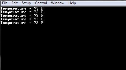
- Also, notice the LED1 blinking at a one second rate
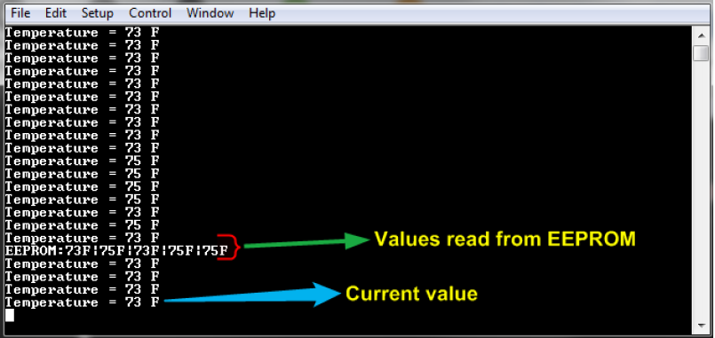
- Press any character on the terminal to display the last five values written to the EEPROM
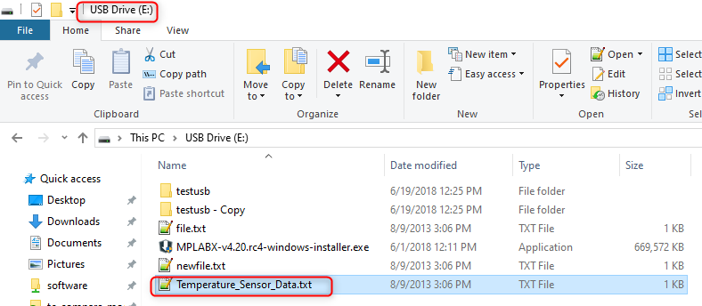
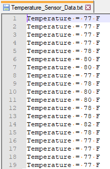
- You should see the LED2 is in “ON” state whenever you connect a USB thumb drive and the application creates a text file “Temperature_Sensor_Data.txt” if it is not already present in the USB thumb drive. The latest room temperature samples are written to the text file at a one-second rate. To view the data in the text file, connect the USB Thumb drive to a PC USB port and open the Temperature_Sensor_Data.txt file
- You may vary the temperature by placing your finger on the temperature sensor (for a few seconds)
Comments:
- Reference Training Module: Getting Started with Harmony v3 Drivers and Middleware on PIC32MZ EF MCUs using FreeRTOS
- This application demo builds and works out of box by following the instructions above in “Running the Demo” section. If you need to enhance/customize this application demo, you need to use the MPLAB Harmony v3 Software framework. Refer links below to setup and build your applications using MPLAB Harmony.
- How to Setup MPLAB Harmony v3 Software Development Framework
- How to Build an Application by Adding a New PLIB, Driver, or Middleware to an Existing MPLAB Harmony v3 Project
- MPLAB Harmony v3 is also configurable through MPLAB Code Configurator (MCC). Refer to the below links for specific instructions to use MPLAB Harmony v3 with MCC.
Revision:
- v1.6.0 - Regenerated and tested the application
- v1.5.0 - Removed MHC support, regenerated and tested application.
- v1.4.0 - Added MCC support, regenerated and tested application.
- v1.3.0 - Regenerated and tested application.
- v1.2.0 - Regenerated and tested application.
- v1.1.0 - Regenerated and tested application.
- v1.0.0 - Released demo application