![]()
![]()
SD Card, USB Data Logger Application on SAM D21 Xplained Pro Evaluation Kit
Download
Description
This application shows an example of using the MPLAB Harmony v3 File System to store the sensor data (light intensity values) into a SD card using the SDSPI and a SPI driver. The SD card is also enumerated as a MSD(Mass Storage Device) device on the PC(USB Host) enabling logged data viewing.
The SDSPI driver uses an instance of the SPI driver to communicate to the SD card over the SPI bus. The application creates a directory named Dir1 in the root directory and creates a new file named LS_LOG.txt. The application writes the light sensor values into this newly created file when the user presses the switch button SW0. If the directory and file already exists the values are logged into the existing file itself. The logged light intensity values are read via USB with the SD card enumerated as an MSD( Mass Storage Device). The application parallelly continues to log the sensor data with the SD card enumerated as an MSD.
Modules/Technology Used:
- Peripheral Modules
- Timer
- DMAC
- ADC
- PORTS
- EVENT SYSTEM
- SERCOM (USART)
- SERCOM (SPI)
- RTC
- Drivers
- SDSPI Driver
- USB Full Speed Driver
- SPI Driver
- SDSPI Driver
- Libraries
- USB MSD Library
- File System Library
- Debug System service Library
- STDIO Library
Hardware Used:
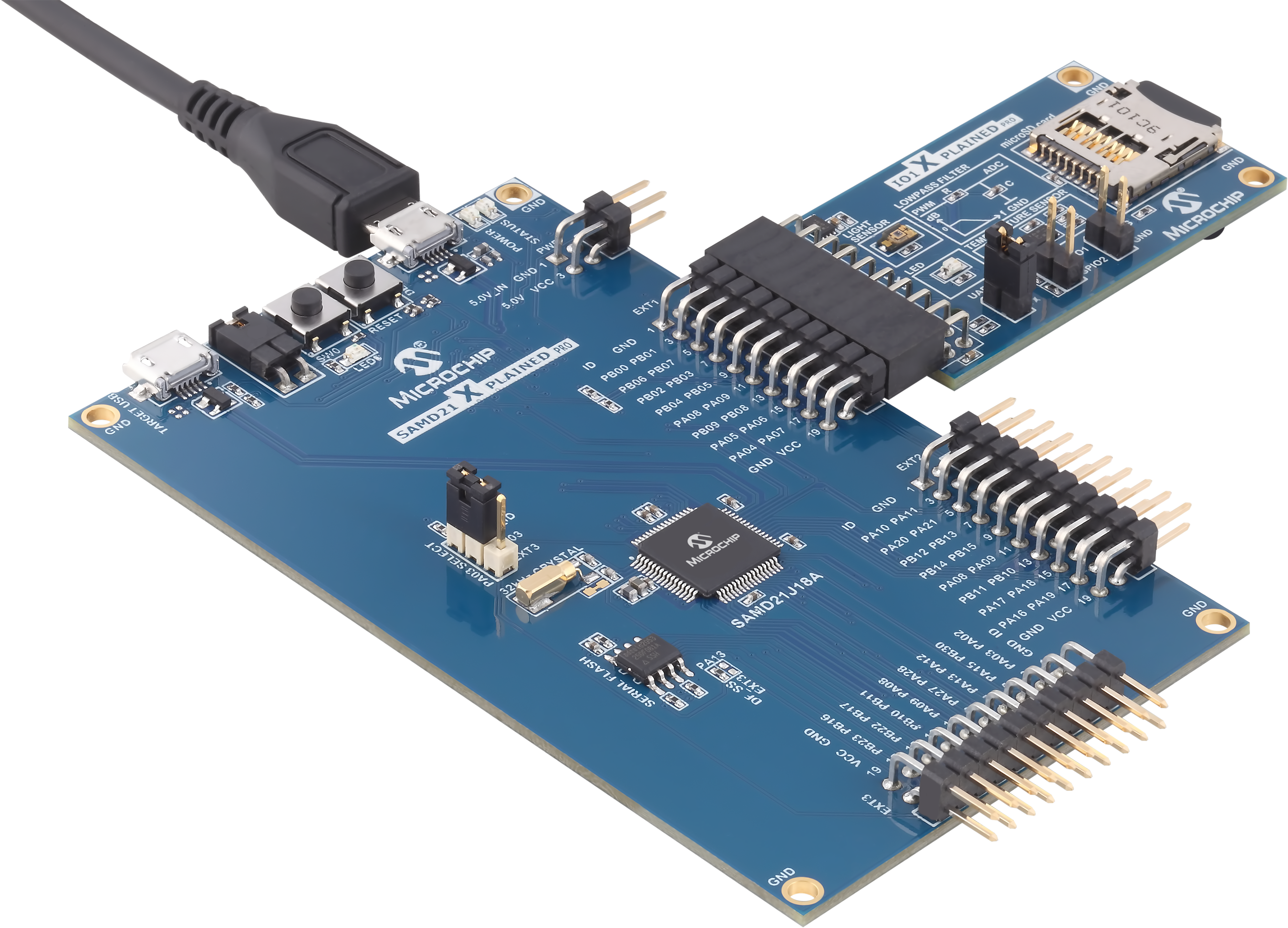
- SAM D21 Xplained Pro Evaluation Kit
- I/O1 Xplained Pro Extension Kit
- Micro-SD card formatted to FAT32 filesystem.
Software/Tools Used:
This project has been verified to work with the following versions of software tools:
Refer Project Manifest present in harmony-manifest-success.yml under the project folder firmware/src/config/sam_d21_xpro
- Refer the Release Notes to know the MPLAB X IDE and MCC Plugin version.Alternatively, Click Here
- Any Serial Terminal application like Tera Term terminal application.
Because Microchip regularly update tools, occasionally issue(s) could be discovered while using the newer versions of the tools. If the project doesn’t seem to work and version incompatibility is suspected, It is recommended to double-check and use the same versions that the project was tested with. To download original version of MPLAB Harmony v3 packages, refer to document How to Use the MPLAB Harmony v3 Project Manifest Feature
Setup:
-
Verify that the Light sensor (in I/O1 Xplained Pro Extension Kit) is connected to Extension Header 1 (EXT1) on the SAM D21 Xplained Pro Evaluation Kit
-
Insert microSD(upto 32GB) card on to the I/O1 Xplained Pro Extension Kit
-
The SAM D21 Xplained Pro Evaluation Kit allows using the Embedded Debugger (EDBG) for debugging. Connect the Type-A male to micro-B USB cable to micro-B DEBUG USB port to power and debug the SAM D21 Xplained Pro Evaluation Kit
Programming hex file:
The pre-built hex file can be programmed by following the below steps
Steps to program the hex file
- Open MPLAB X IDE
- Close all existing projects in IDE, if any project is opened.
- Go to File -> Import -> Hex/ELF File
- In the “Import Image File” window, Step 1 - Create Prebuilt Project, click the “Browse” button to select the prebuilt hex file.
- Select Device has “ATSAMD21J18A”
- Ensure the proper tool is selected under “Hardware Tool”
- Click on “Next” button
- In the “Import Image File” window, Step 2 - Select Project Name and Folder, select appropriate project name and folder
- Click on “Finish” button
- In MPLAB X IDE, click on “Make and Program Device” Button. The device gets programmed in sometime.
- Follow the steps in “Running the Demo” section below
Programming/Debugging Application Project:
- Open the project (samd21_sdcard_usb_datalogger/firmware/sam_d21_xpro.X) in MPLAB X IDE
- Ensure “SAM D21 Xplained Pro” is selected as hardware tool to program/debug the application
- Build the code and program the device by clicking on the “Make and program” button in MPLAB X IDE tool bar
- Follow the steps in “Running the Demo” section below
Running the Demo:
-
Press the switch button SW0 to log light intensity values from the light sensor into the SD card.
-
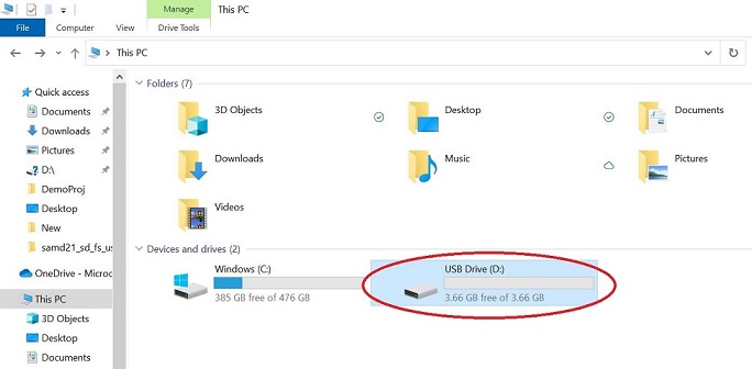
To read the logged light intensity values, connect the Target USB port on the board to the computer using a micro USB cable.
-
LED0 is illuminated when SD card is enumerated as a Mass Storage Device by the USB host.(see below image)
-
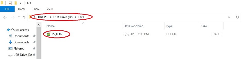
Access the LS_LOG.txt via USB inside the Dir1 folder.(see below image)
-
The sample log file looks as below.

- Always eject the USB drive before removing it.
Comments:
- Reference Training Module:
- This application demo builds and works out of box by following the instructions above in “Running the Demo” section. If you need to enhance/customize this application demo, you need to use the MPLAB Harmony v3 Software framework. Refer links below to setup and build your applications using MPLAB Harmony.
- How to Setup MPLAB Harmony v3 Software Development Framework
- How to Build an Application by Adding a New PLIB, Driver, or Middleware to an Existing MPLAB Harmony v3 Project
- MPLAB Harmony v3 is also configurable through MPLAB Code Configurator (MCC). Refer to the below links for specific instructions to use MPLAB Harmony v3 with MCC.
Revision:
-
v1.6.0 - Regenerated and tested application.
-
v1.5.0 - Removed MHC support, Regenerated and tested application.
-
v1.4.0 - Released demo application