Note:
This guide will explain how to use SAM-BA to Write Boot Configuration Packet & Flash at91bootstrap, RTOS/Baremetal applications to external NVM for SAMA7G54.
Introduction
This document will guide the user on how to,
- Write boot sequence controller configuration register (BSC_CR) & boot configuration packet to configure first stage bootloader.
- Flash boot.bin (at91bootstrap) & harmony.bin (RTOS/Baremetal application) file to external NVMs like QSPI flash, e.MMC & SD-Card.
Prerequisites
Details
- Familiar with the features of the SAM7G54-EK (board can be evaluation Kit) and understanding about the jumpers & Connectors on the board.
- Install SAM-BA tool on your windows host PC.
- To Download the latest version of SAM-BA tool for Windows click this link.
- Download the ZIP file and unzip it into a working directory of your choice.
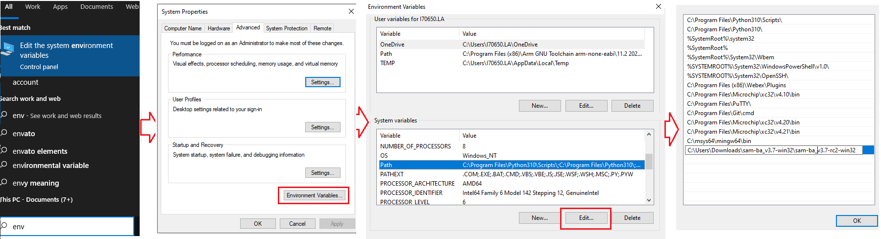
- Add the SAM-BA directory path to the environment variables.
- To do this from your PC –> Open the Start Search, type in “env”.
- Choose “Edit the system environment variables” –> Click “Environment Variables” –> “System Variables” –> add SAM-BA directory path to path variables.
- Once the SAM-BA Host program has been installed, the execution of the application is from the Windows command prompt.
-
Refer this link to configure and build the at91bootstrap to load the application from the user preferred NVM like QSPI flash, e.MMC & SDCard.
Note: This resultant at91bootstrap file (boot.bin) built with the preferred NVM configuration only to be used here.
- Refer this link to build harmony application.
Setup SAM-BA Host to Monitor Communications
Details
In this section you will establish SAM-BA Host Application communications with the target’s (SAMA7G54) SAM-BA Monitor. Then you will use the SAM-BA Host Applet (qspiflash) to erase and then write the boot.bin (at91bootstrap) and harmony.bin (MPLAB Harmony 3 application) binary images to NOR Flash Memory.
Step 1: To communicate with the SAM-BA Monitor on the target, you must have installed the SAM-BA Host on a Host Computer.
Step 2: Ensure there is no SD memory card inserted.
Step 3: Power the board by connecting a Micro-B USB cable to USBA port (J7) on the SAMA7G54-EK.
Step 4: Establish UART serial communication with PC through J24 on SAMA7G54 Evaluation Kit.
Step 5: Open Disable boot Jumper(J22) on SAMA7G54 Evaluation Kit.
Step 6: Follow below steps for SAMA7G54 Evaluation Kit:
- Push and hold the “DISABLE BOOT” button. (This disables booting from the onboard memories - e.MMC Flash, SDCARD and QSPI flash Memory).
- Reset the board by pressing and then releasing the reset “nRST” button.
- Release the “DISABLE BOOT” button.
Now, the SAMA7G54-EK will boot to the SAM-BA Monitor and start communications with the SAM-BA Host Application.
Note:
-
SAM-BA communication Port can be j-link, serial or secure.
-
If user wants to program the SAMA7G54 Evaluation Kit, using j-link instead of serial UART port, then connect J24 with PC via USB cable and replace “serial” in SAM-BA commands with “j-link”.
- Eg: Replace sam-ba -p serial -b sama7g5-ek -a lowlevel with sam-ba -p j-link -b sama7g5-ek -a lowlevel
1. Program External QSPI flash memory
Details
1.1. Erase QSPI flash memory
Erase the contents of the QSPI Flash memory on the SAMA7G54-EK with the following command:
sam-ba -p j-link -b sama7g5-ek -a qspiflash -c erase
Example:

1.2. Program boot.bin to QSPI flash memory
Program the boot.bin file on the SAMA7G54-EK with the following command:
sam-ba -p j-link -b sama7g5-ek -a qspiflash -c writeboot:boot.bin
- Note: Change directory to the location of boot.bin
Example:

Note: Refer this link to configure and build the at91bootstrap to load the application from QSPI.
The at91bootstrap file (boot.bin) built with QSPI configuration only to be used here.
1.3. Program harmony.bin to QSPI flash memory
To program the application binary, harmony.bin file on the SAMA7G54-EK, use the following command:
sam-ba -p j-link -b sama7g5-ek -a qspiflash -c write:harmony.bin:QSPI_OFFSET
Note:
* The QSPI_OFFSET should be the same offset used in the KCONFIG, while configuring the at91bootstrap to load from external QSPI
* Change directory to the location of harmony.bin.
Example:

Note:
To learn about more SAM-BA applet commands, refer your SAM-BA installation directory/doc/applet.html
2. Program External e.MMC Flash Memory
Details
To boot from e.MMC flash memory, we need to flash sdcard.img file in user partition area in e.MMC flash memory.
2.1. Create sdcard.img file for boot.bin and harmony.bin.
To create .img file we need an SDCARD and a windows tool named Win32DiskImager. Click here to download the tool.
- First Partition the SDCARD with size of 4MB and format SDCARD with FAT or FAT32 file system.
- Now place the boot.in and harmony.bin in SDCARD.
- Install Win32DiskImager Tool and open the tool.
- In Device tab, select the drive for which the image file needs to be created.

- In ImageFile tab, enter the path and file name with extention(.img) to store the generated image file.

- Now select the check box next to Read Only Allocated Partitions and click on Read button.

- When reading is completed, a pop-up window will be displayed with status as Read Successful.

- Now the generated image(.img) file will be available in above mentioned location.
- In Device tab, select the drive for which the image file needs to be created.
2.2. Program sdcard.img file to e.MMC flash memory
To program the sdcard.img file on the SAMA7G54-EK with the following command:
sam-ba -p j-link -b sama7g5-ek -a sdmmc -c write:sdcard.img
Example:

Note: Refer this link to configure and build the at91bootstrap to load the application from e.MMC flash memory.
The at91bootstrap file (boot.bin) built with e.MMC configuration only to be used here.
Note:
To learn about more SAM-BA applet commands, refer your SAM-BA installation directory/doc/applet.html
3. Program External SD CARD
Details
To program the at91bootstrap -boot.bin file and application binary -harmony.bin file on SD-card:
- (i) Format the SD card using your PC/Laptop.
- (ii) Copy and paste boot.bin and harmony.bin into the SD card from your host PC.
Note: Refer this link to configure and build the at91bootstrap to load the application from SD Card.
The at91bootstrap file (boot.bin) built with SD card configuration should be used here.
4. Program BSC_CR & Boot Configuration Packet
Details
After a reset, The ROM code reads the Boot Configuration Packet from the SRAM dedicated to Emulation mode if the bit BSC_CR.EMUL_EN is set to 1 or from the OTP matrix and configure boot sequence, Enable/Disable Monitor, configure the serial console UART.
Using Emulated OTP enables the user to test several boot configuration options, including secure boot mode without programming the OTP.
Note: If Emulation mode is enabled, the emulation SRAM is not backed up. After a power off/on, the configuration and content are lost.
4.1. Enable/Disable Emulation mode in BSC_CR
To Enable/Disable Emulation mode in Boot Sequence Controller Configuration Register (BSC_CR), the following SAM-BA command should be used:
To Enable Emulation Mode:
sam-ba -p j-link -b sama7g5-ek -a bootconfig -c writecfg:bscr: EMULATION_ENABLED
To Disable Emulation Mode:
sam-ba -p j-link -b sama7g5-ek -a bootconfig -c writecfg:bscr: EMULATION_DISABLED
4.2. Steps to write Boot Configuration Packet to emulated SRAM
- Emulation enable : sam-ba -p j-link -b sama7g5-ek -a bootconfig -c writecfg:bscr:EMULATION_ENABLED
- Reset : sam-ba -p j-link -b sama7g5-ek -a bootconfig -c resetemul
- Refresh config : sam-ba -p j-link -b sama7g5-ek -a bootconfig -c refreshcfg:emul
- Write Config : sam-ba -p j-link -b sama7g5-ek -a bootconfig -c writecfg:bcp-emul:DBGU,SDMMC0_IOSET1
- Lock config : sam-ba -p j-link -b sama7g5-ek -a bootconfig -c lockcfg:bcp-emul
4.3. Steps to write Boot Configuration Packet to OTP
- Emulation disable: sam-ba -p j-link -b sama7g5-ek -a bootconfig -c writecfg:bscr:EMULATION_DISABLED
- Refresh config : sam-ba -p j-link -b sama7g5-ek -a bootconfig -c refreshcfg:otp
- Write Config : sam-ba -p j-link -b sama7g5-ek -a bootconfig -c writecfg:bcp-otp:DBGU,SDMMC0_IOSET1
- Lock config : sam-ba -p j-link -b sama7g5-ek -a bootconfig -c lockcfg:bcp-otp
4.4. Boot Configuration Packet different configurations available
The writecfg command programs the Boot Configuration Packet (BCP) into the Emulated SRAM, if the emulation mode of the OTPC is enabled. Else BCP packets are stored inside the OTP matrix.
User can use the below command to get the full list of boot configurations possible:
sam-ba -p j-link -b sama7g5-ek -a bootconfig -c writecfg:help
Example boot configurations:
boot config with Serial Console on FLEXCOM0, boot from SDMMC1 store in OTP matrix
sam-ba -p j-link -b sama7g5-ek -a bootconfig -c writecfg: bcp-otp:FLEXCOM0_USART_IOSET1,SDMMC1_IOSET1
Empty boot configuration packet in OTP matrix
sam-ba -p j-link -b sama7g5-ek -a bootconfig -c writecfg: bcp-otp:
Boot config with SAM-BA Monitor Disabled, boot from SDMMC1 store in OTP-Emulation mode
sam-ba -p j-link -b sama7g5-ek -a bootconfig -c writecfg: bcp-emul:MONITOR_DISABLED,SDMMC1_IOSET1
Empty boot configuration packet in OTP-Emulation mode- Emulated SRAM
sam-ba -p j-link -b sama7g5-ek -a bootconfig -c writecfg: bcp-emul:
Note:
To learn about more bootconfig SAM-BA applet commands: Refer your SAM-BA installation directory/doc/bootconfig-otp.html
Links
- Click here to learn how to configure first stage bootloader for SAMA7G54 MPU
- Click here to learn how to configure/built and debug second stage bootloader(at91bootstrap) for SAMA7G54 MPU