Create “Hello World” application on SAM MCUs
Introduction
MPLAB Harmony v3 is a software development framework consisting of compatible and interoperable modules that include peripheral libraries (PLIBs), drivers, system services, middleware and third-party libraries. The MPLAB Code Configurator (MCC) is a GUI-based tool that provides an easy way to enable and configure various MPLAB Harmony modules. The MCC is a plug-in to the MPLAB X Integrated Development Environment (IDE). This page explains how to create a simple application on an Arm® Cortex®-based SAM Microcontroller (MCU) using the MCC with MPLAB Harmony v3 modules. This application sends a “Hello World!” string to a console running on a computer. For this demonstration, the following MPLAB Harmony v3 modules are used and configured using the MCC:
- Clock PLIB using the Clock Manager to configure the microcontroller clock.
- PORT PLIB using the Pin Manager to configure the microcontroller I/Os.
- Serial Communication (SERCOM) USART PLIB to configure USART peripheral as serial port.
Required Software
The instructions in this tutorial assume that you have already installed following software.
Required Hardware
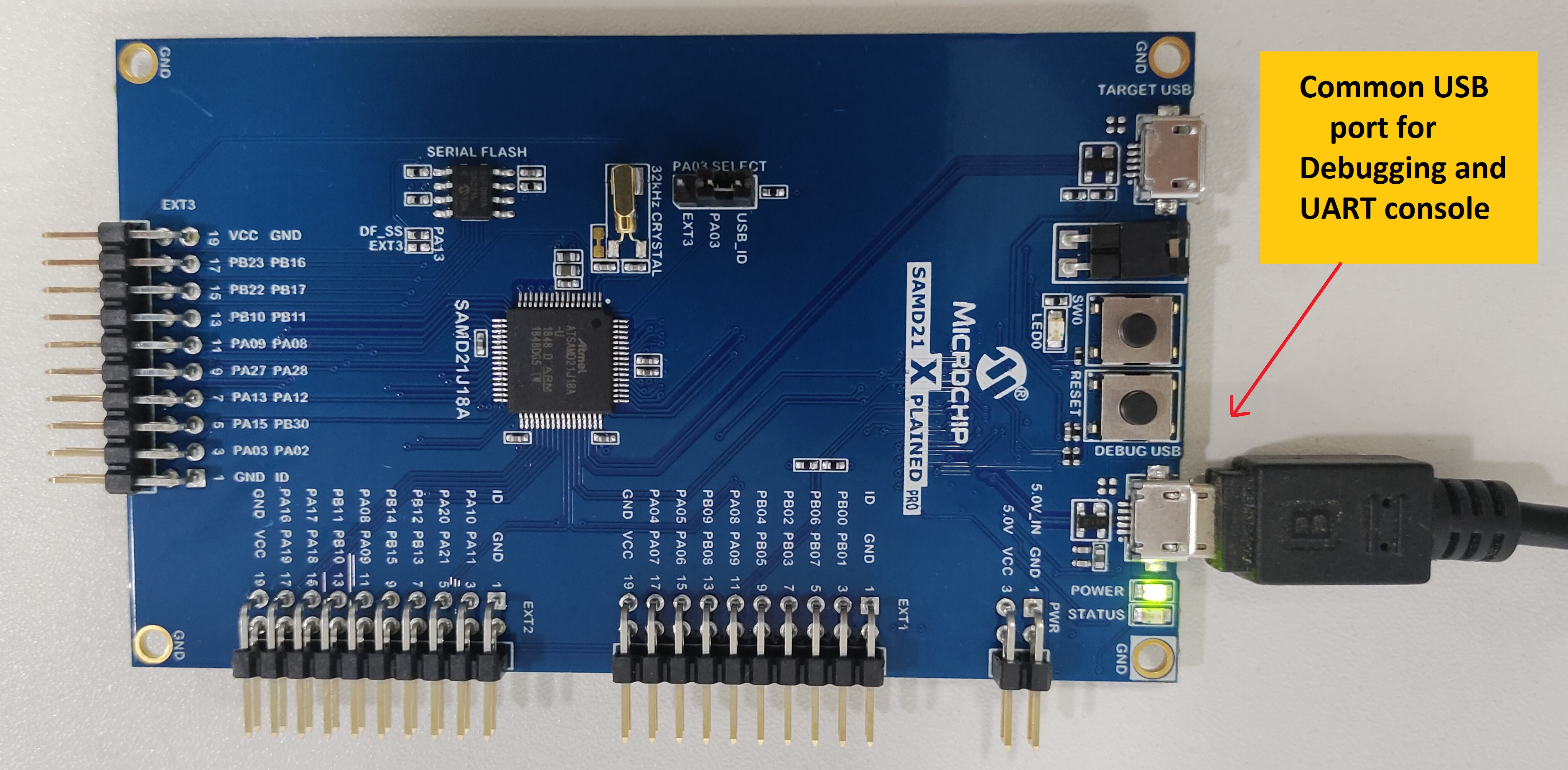
The instructions in this tutorial use SAMD21 Xplained Pro board and it has one Yellow Color user LED (PB30) connected GPIO. Similar kits will work similarly, but the setup and steps may not be exactly as described.
Setup: The following figure shows the hardware setup details:
-
Connect SAMD21 Xplained Pro Board micro USB port to PC using a micro USB cable
Procedure
Step 1: To create an MPLAB Harmony v3-based project, follow these steps:
The following are the steps to create, generate, build and flash LED Blinking application. Before proceeding, make sure you have downloaded the required Harmony 3 packages (for directions, the MPLAB® Code Configurator (MCC) User’s Guide) and setup the required hardware as shown previously.
Create a new project
- Open the MPLAB® X IDE.
- Create a New Project by clicking the New Project icon
 or by selecting File > New Project.
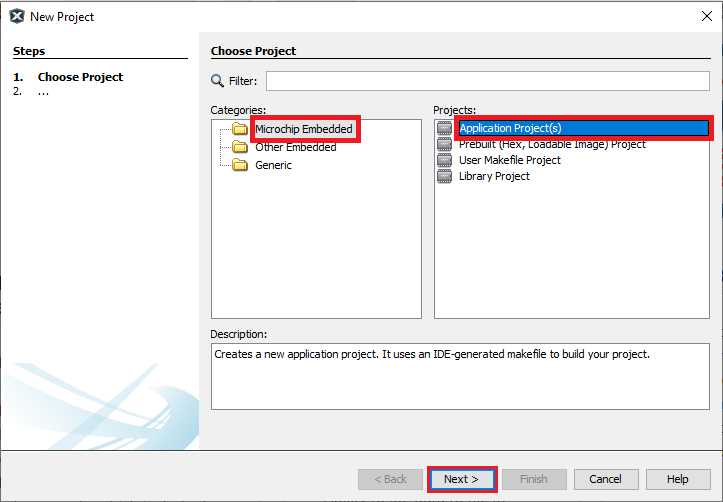
 - In the New Project window select Application Project(s).
-
Click Next.
Note:
- If the option 32-Bit MPLAB Harmony v3 Project is not available, install the MPLAB® Harmony 3 Launcher plug-in from Tools > Plugins > Available Plugins before continuing with this demonstration.
-
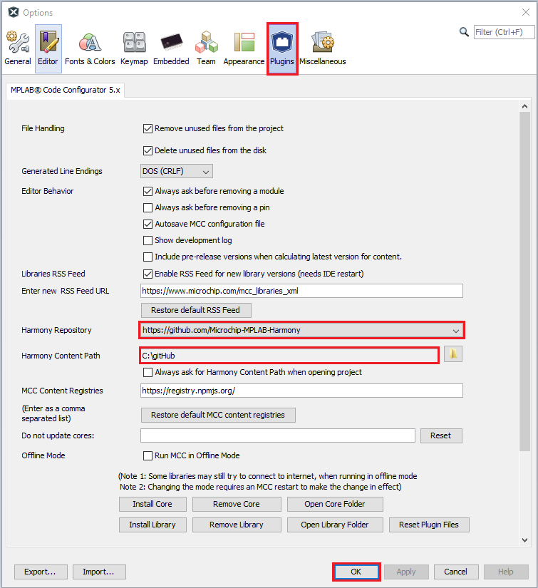
If the Harmony Content Path and Repository is not set, then go to Tools > Options, select Pugins and select the Harmony Repository and enter the your Harmony Content Path as shown in the below figure to download the Harmony packages.
-
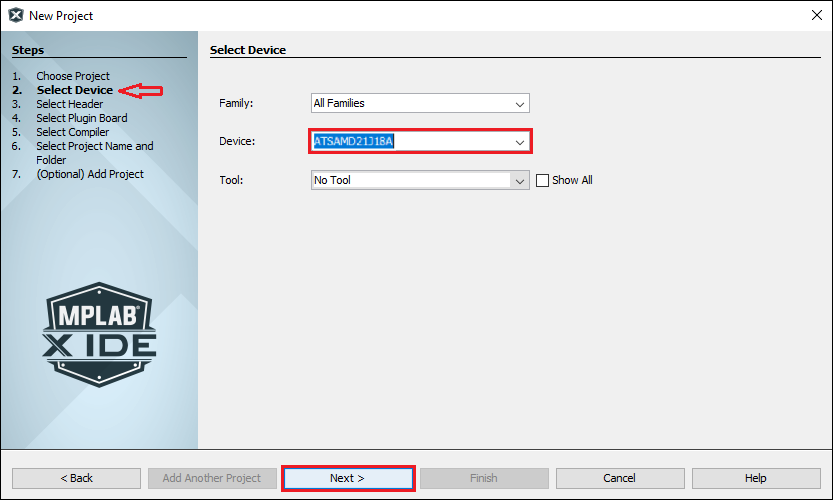
In the Select Device dialog window, select the target Device ATSAMD21J18A from the drop-down menu as shown below and Click Next.
-
In the Select Compiler dialog window, select the latest or needed Compiler as follows:
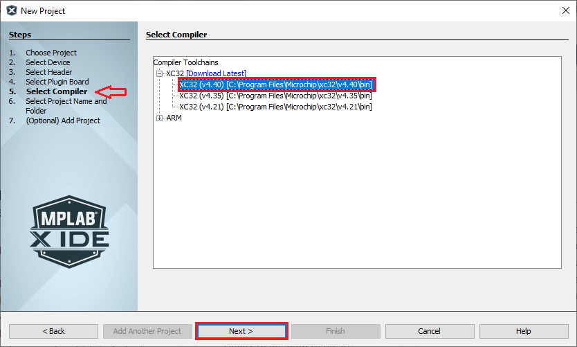
- Click Next.
- In the Select Project Name and Folder dialog window, fill in or select the information needed as follows:
- Project Name: Project naame i.e. “sam_d21_xpro”
- Project Location: Select or Enter the Project Location of your choice.
- For Example: sam_d21_hello and the Project Location is:
C:/Users/<user_id>/MPLABXProjects/sam_device/sam_d21_01/firmware
- Note: Kindly suffix the firmware folder name after the Project folder “sam_d21_01”.
- For Example: sam_d21_hello and the Project Location is:
- Project Folder: This is a read-only field, MCC automatically creates the .X project folder in the above mentioned project location.
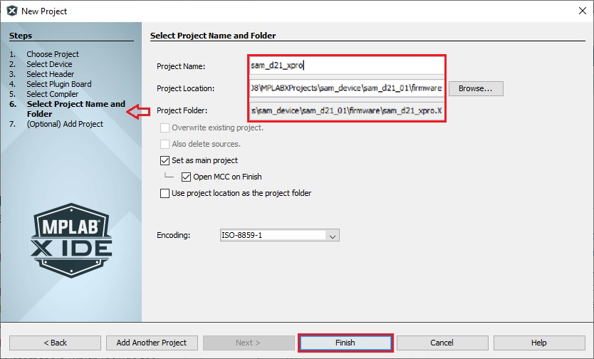
- Click Finish.
- Download the Required Mandatory Harmony Content if not downloaded.
-
The below MCC Content Manager window will open if the Mandatory Harmony Contents are not present in the Harmony Content Path mentioned in the Step 4.
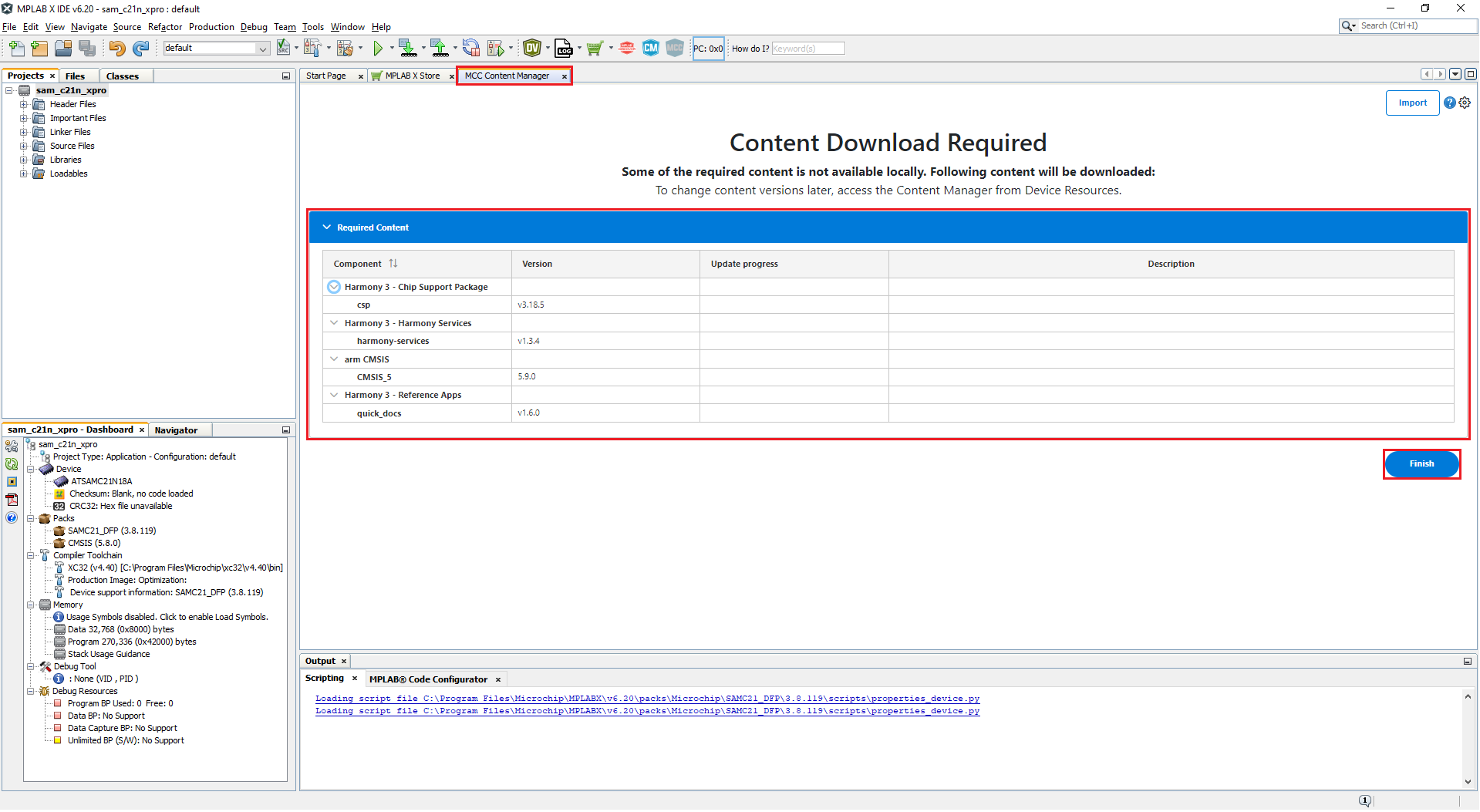
- Click on the Finish Button in the MCC Content Manager Wizard to start downloading the Mandatory Harmony Content.
- Note: For this demonstration application, the following MPLAB Harmony v3 packages are required: csp, harmony-services, CMSIS, and quick_docs. The MPLAB Harmony 3 Content Manager tool simplifies the downloading of the MPLAB Harmony v3 packages. If these packages are not downloaded, then the user can use the MPLAB Harmony 3 Content Manager tool to download them onto their computer.
-
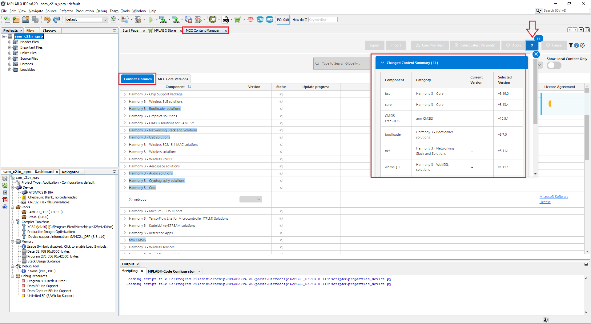
If you need you can select the optional contents like bsp, core, CMSIS-FreeRTOS, etc and click apply, then Content Manager will start downloading these selected packages under the Harmony Content path.
-
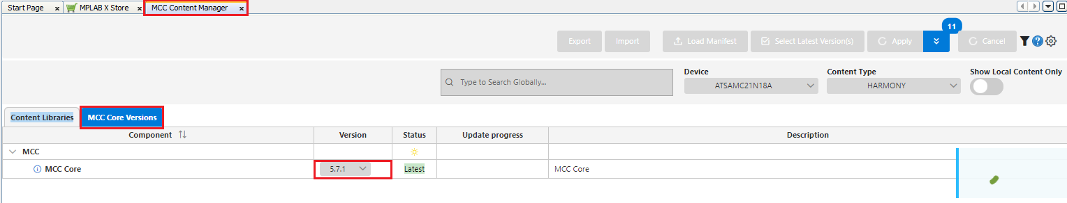
Similarly, update the MCC Core Versions to the latest if not already updated.
-
-
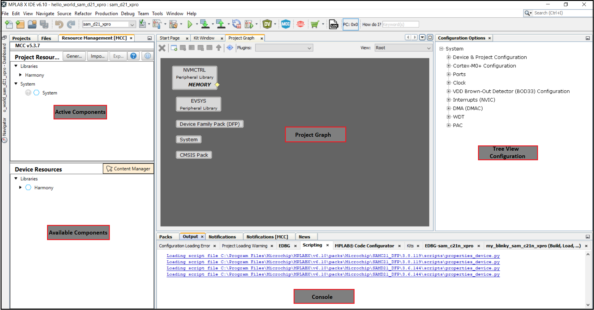
- The MCC plug-in will open in a new window. The image below highlights different section available in the MCC.
Step 2: To add and configure the MPLAB Harmony components using the MCC, follow these steps:
-
Launch the Clock Configuration manager by clicking Project Graph > Plugins > Clock Configuration.
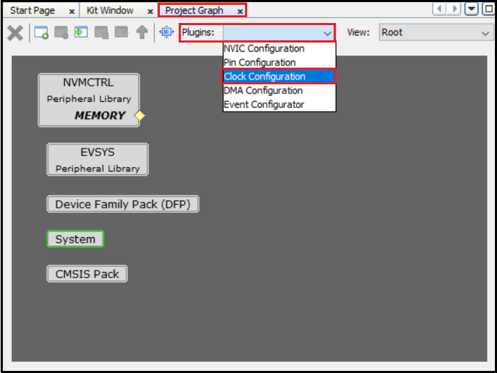
The Clock Easy View window will be displayed inside the MCC Window.
-
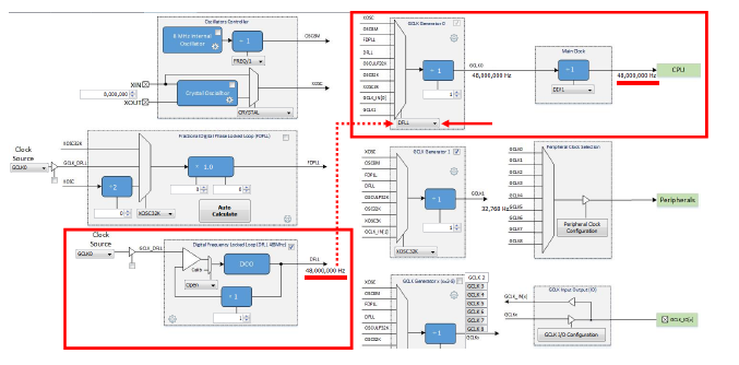
In the Clock Easy View window, scroll to the right and verify that the Main Clock is set to 48 MHz.
- To add and configure the USART Peripheral Library follow these steps:
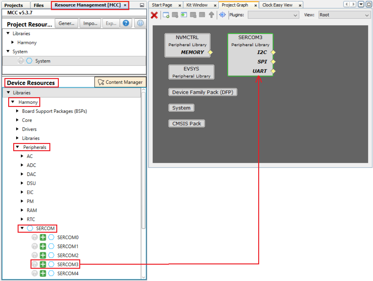
- Click on the Resource Management [MCC] tab, In the Device Resources , expand Harmony > Peripherals > SERCOM.
- Double-click on the SERCOM3 to add it to the project
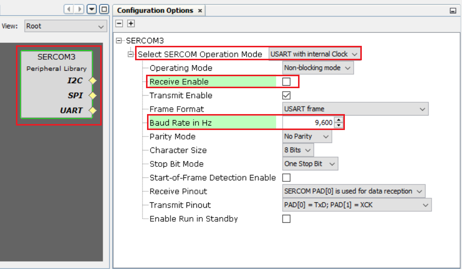
- Select the SERCOM3 Peripheral Library in the Project Graph, and in the Configuration Options window, configure it as follows:
- SERCOM Operation mode is set for USART with Internal Clock (default setting).
- Clear Receive Enable, as the string will only be transmitted in this example.
- Set the Baud Rate to 9600.
- For Transmit Pinout choose SERCOM PAD[0] (default setting).
- By default, the Receive Pinout is SERCOM PAD[0]. If the Receive Pinout feature is disabled, it will not affect the operation.
-
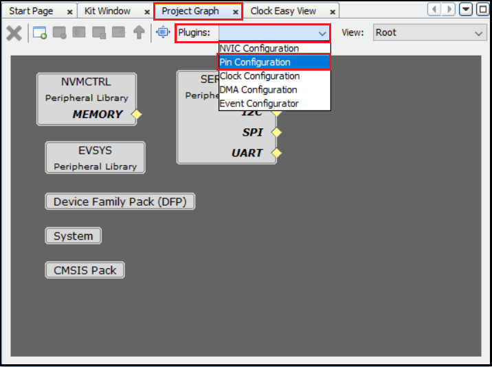
Configure the USART pin in the Pin Settings: In the MCC, select Project Graph > Plugins > Pin Configuration to open the Pin Settings window.
-
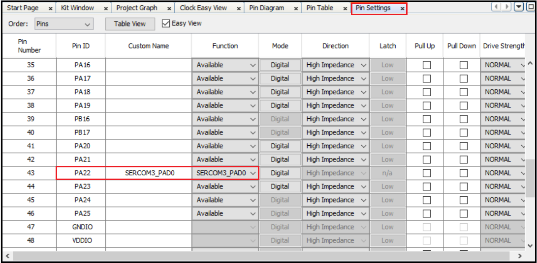
The MCC Pin Settings window will open and display these options: Pin Diagram, Pin Table, and Pin Settings.
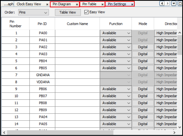
Note: According to the schematic of the SAMD21 Xplained Pro board, the on-board Embedded Debugger (EDBG) can be used as Virtual Com Port to have serial communication between the SAMD21 device and a connected computer console. Therefore, the PA22 (Pin #43) of the SAMD21 must be configured as USART_TX (SERCOM3 PAD0).
-
Click the Pin Settings tab and configure the PA22 pin as SERCOM3_PAD0.
-
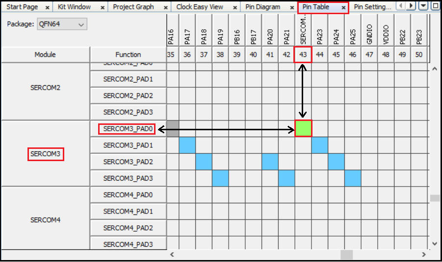
The same pin (PA22) can be configured by clicking the Pin Table tab.
Note:
- The USART_TX function (Transmit Pinout) is by default configured to be on SERCOM3 PAD0, for additional information, refer to MCC SERCOM Configuration.
- In the SERCOM3 USART configuration, the USART is enabled only for transmit functionality. Therefore, the USART receive pin is not configured.
Step 3: To generate the code, follow these steps:
-
Generate the code by using MCC. From the left side tab, Resource Management (MCC), go to Project Resources and click on the Generate button.
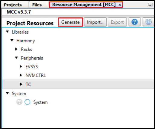
- The above step triggers these actions in MCC:
- Generate the code as per the configurations done.
- Place the generated code and required MPLAB Harmony framework files in the MPLAB Harmony project directory, in this case: *C:/Users/
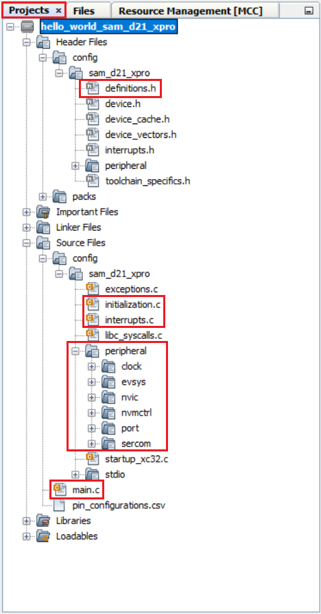
/MPLABXProjects/sam_device/sam_d21_01/firmware/src*. - Add all generated codes and MPLAB Harmony framework files into the MPLAB Harmony project, as shown in the following figure.
Note: The MPLAB Harmony project will be shown in another window as this project is in Standalone mode.
-
The generated code descriptions are as follows:
- definitions.h: Includes all the header files required for the project.
- initialization.c: Initializes all the MPLAB Harmony modules used in the application.
- interrupts.c: Contains the mapping of all the interrupt vectors on the selected device.
- main.c: A function call to initialize the system present in this file. The user needs to develop their application in this file.
- peripheral: All peripheral source codes are added in this folder.
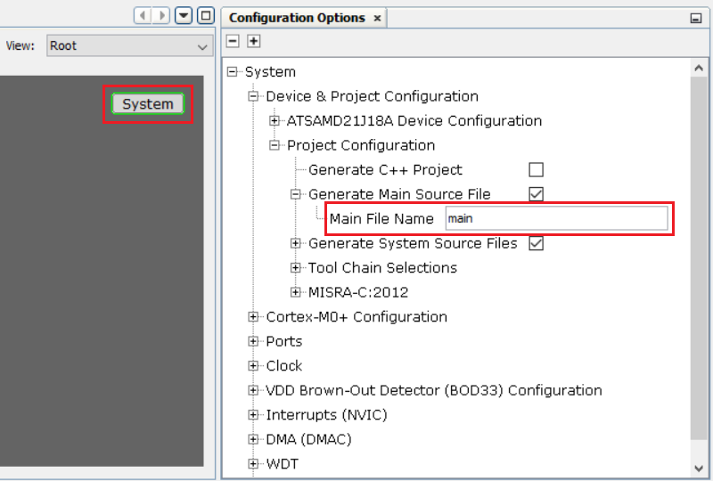
Note: The MCC provides an option to change the generated file name, and if this option is not used, by default, the file name main.c is generated.
Step 4: To develop and run an application, follow these steps:
-
Developing an application: For this demo application, add the highlighted codes (as shown in image below) in the main.c file. This will send the “Hello World!” string to the console running on the PC. The following code is provided for convenience:
 uint8_t buffer[]= "Hello World!\r\n";

 SERCOM3_USART_Write(&buffer[0], sizeof(buffer));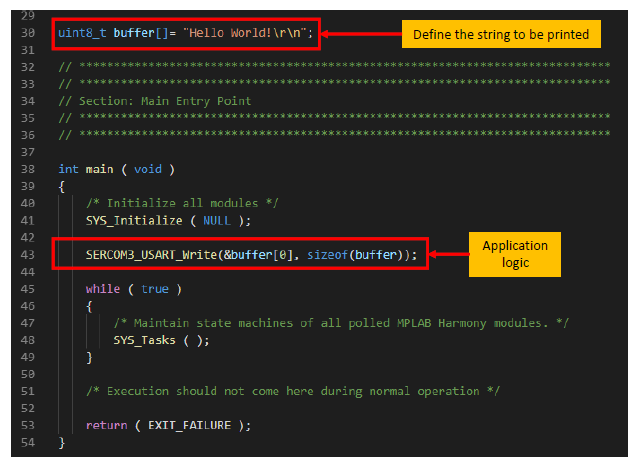
- Selecting Hardware Tool and Compiler: In the MPLAB X IDE Project Properties window perform these actions:
-
Under Categories section, select Conf: (sam_d21_xpro), and in the Configuration section, select the hardware tool and compiler toolchain.
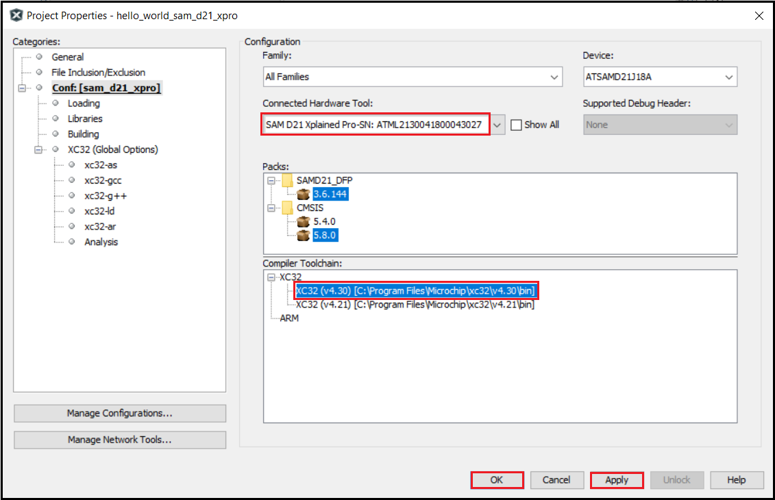
- Click OK.
-
Connecting Hardware: Connect a micro-USB cable between the DEBUG USB on the board and the PC. This enables the programming of the microcontroller and provide a serial connection with the console device (computer).
-
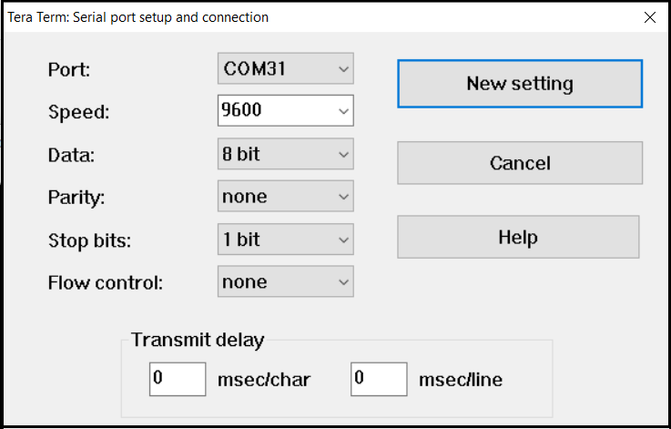
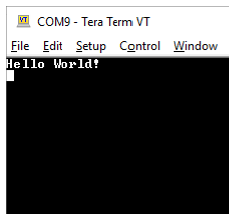
Setting up the Serial Console: Open a terminal application, such as Tera Term on the PC and perform the serial port setup. Below is the default setup details for Tera Term.
-
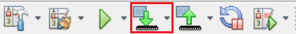
Programing and Running the Application: Build and program the SAMD21 Xplained Pro kit by using the MPLAB X IDE.
-
Observing the Output: Observe the “Hello World!” string on the console. If the desired output is not found on the console, press the Reset button on the Xplained Pro board to reset the device, and ensure that the UART message is communicated.
Note
This page has been verified with the following versions of software tools:
- MPLAB X IDE v6.20
- MPLAB XC32 Compiler v4.40
- MPLAB Code Configurator Plugin v5.5.1
- MPLAB Harmony v3 “csp” repo v3.18.5
Because Microchip regularly update tools, occasionally there could be minor differences with the newer versions of the tools.