Create First MPLAB Harmony 3 Project
Overview
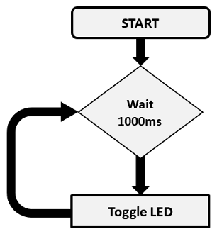
The purpose of this tutorial is to show you how to use Microchip MPLAB® Harmony 3 to create a simple “heartbeat” LED application that flashes an LED using the MPLAB® X IDE and the MPLAB® Code Configurator (MCC). As a bonus, you can reuse the heartbeat LED application in future projects as a simple indicator of system health. This tutorial focuses on direct use of MPLAB® Harmony peripheral libraries to build an application. If you are interested in using interoperable MPLAB® Harmony drivers, services, or middleware in your application, please see “Creating Your First Project – Harmony” when you’ve finished with this tutorial. The application can be defined by the following flowchart:
Required Software
The instructions in this tutorial assume that you have already installed following software.
Required Hardware
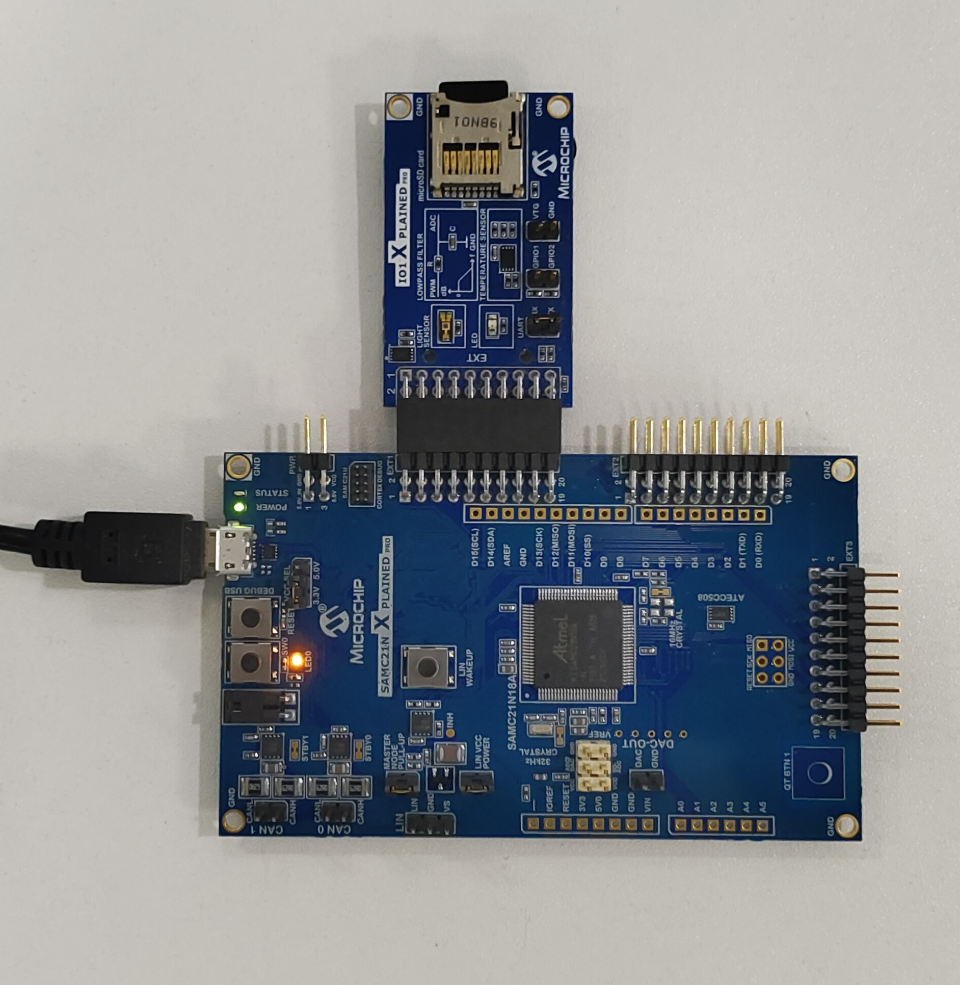
The instructions in this tutorial use SAMC21N Xplained Pro Evaluation Kit and it has one Yellow Color user LED (PC05) connected GPIO. Similar kits will work similarly, but the setup and steps may not be exactly as described.
Setup: The following figure shows the hardware setup details:
-
Connect SAMC21N Xplained Pro Evaluation Kit micro USB port to PC using a micro USB cable
Procedure
The following are the steps to create, generate, build and flash LED Blinking application. Before proceeding, make sure you have downloaded the required Harmony 3 packages (for directions, the MPLAB® Code Configurator (MCC) User’s Guide) and setup the required hardware as shown previously.
Create a new project
- Open the MPLAB® X IDE.
- Create a New Project by clicking the New Project icon
 or by selecting File > New Project.
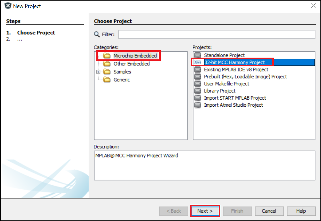
 - In the New Project window select Application Project(s).
-
Click Next.
Note:
- If the option 32-Bit MPLAB Harmony v3 Project is not available, install the MPLAB® Harmony 3 Launcher plug-in from Tools > Plugins > Available Plugins before continuing with this demonstration.
-
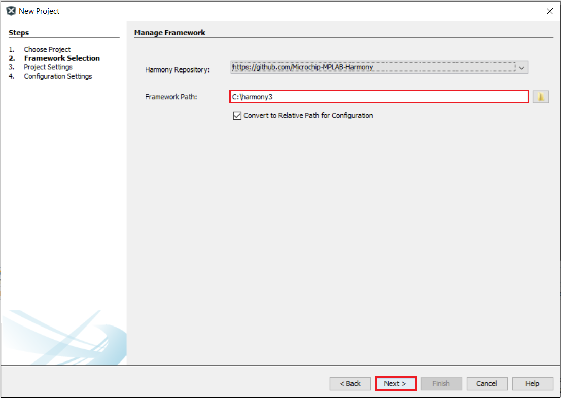
If the Harmony Content Path and Repository is not set, then go to Tools > Options, select Pugins and select the Harmony Repository and enter the your Harmony Content Path as shown in the below figure to download the Harmony packages.

-
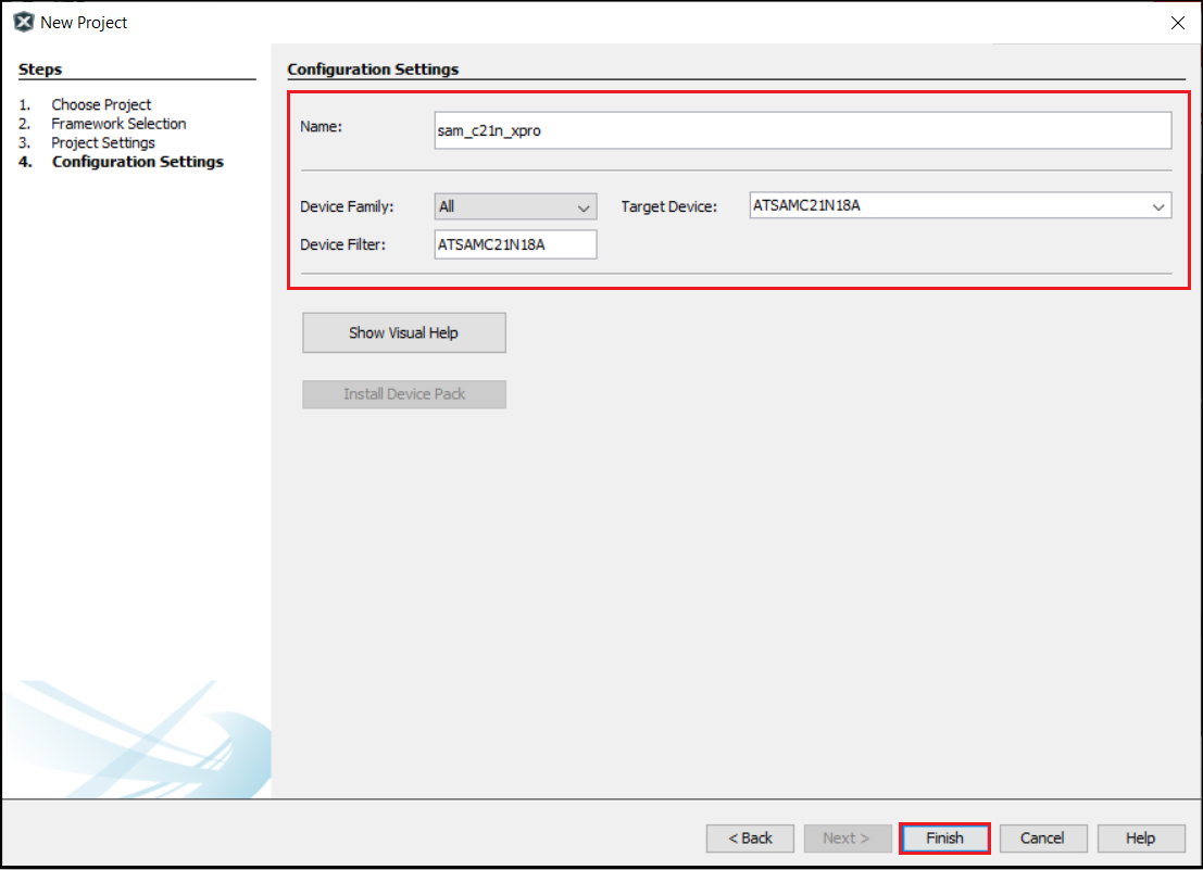
In the Select Device dialog window, select the target Device ATSAMC21N18A from the drop-down menu as shown below and Click Next.
-
In the Select Compiler dialog window, select the latest or needed Compiler as follows:
- Click Next.
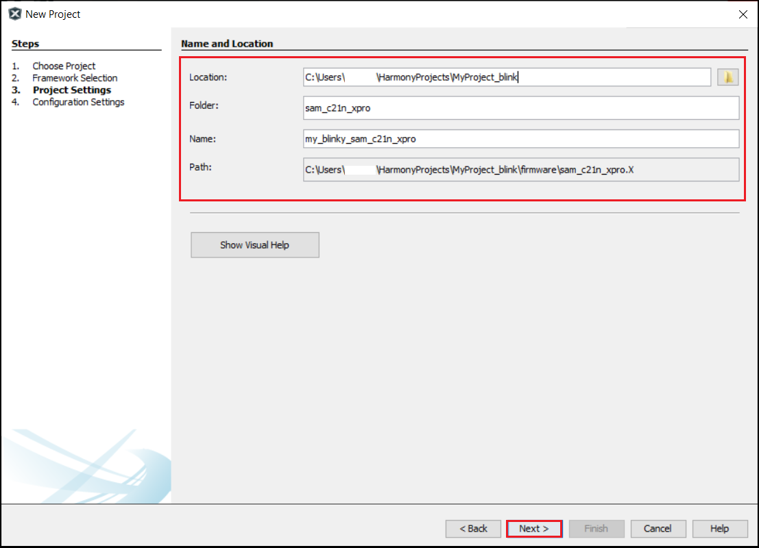
- In the Select Project Name and Folder dialog window, fill in or select the information needed as follows:
- Project Name: Project naame i.e. “sam_c21n_xpro”
- Project Location: Select or Enter the Project Location of your choice.
- For Example: MyProject_blink and the Project Location is:
C:/Users/<user_id>/MPLABXProjects/sam_c21n/MyProject_blink/firmware
- Note: Kindly suffix the firmware folder name after the Project folder “MyProject_blink”.
- For Example: MyProject_blink and the Project Location is:
- Project Folder: This is a read-only field, MCC automatically creates the .X project folder in the above mentioned project location.
- Click Finish.
- Download the Required Mandatory Harmony Content if not downloaded.
-
The below MCC Content Manager window will open if the Mandatory Harmony Contents are not present in the Harmony Content Path mentioned in the Step 4.

- Click on the Finish Button in the MCC Content Manager Wizard to start downloading the Mandatory Harmony Content.
- Note: For this demonstration application, the following MPLAB Harmony v3 packages are required: csp, harmony-services, CMSIS, and quick_docs. The MPLAB Harmony 3 Content Manager tool simplifies the downloading of the MPLAB Harmony v3 packages. If these packages are not downloaded, then the user can use the MPLAB Harmony 3 Content Manager tool to download them onto their computer.
-
If you need you can select the optional contents like bsp, core, CMSIS-FreeRTOS, etc and click apply, then Content Manager will start downloading these selected packages under the Harmony Content path.

-
Similarly, update the MCC Core Versions to the latest if not already updated.

-
-
Setup MPLAB® Harmony Project Configurator to Generate Code
-
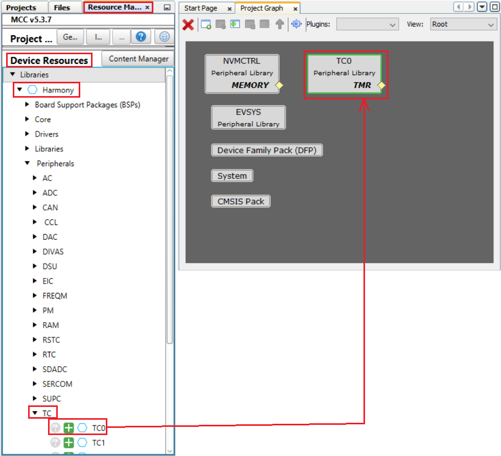
Click on the Resource Management [MCC] tab, In the Device Resources , expand Harmony > Peripherals > TC.
Select and double click on TC0 to add the TC0 to the project.
-
Click on the “TC0” component and configure as below and in the figure:
- Select Prescaler value to “Prescaler: GCLK_TC/1024”
- Set Time (Milli Sec) to “500”
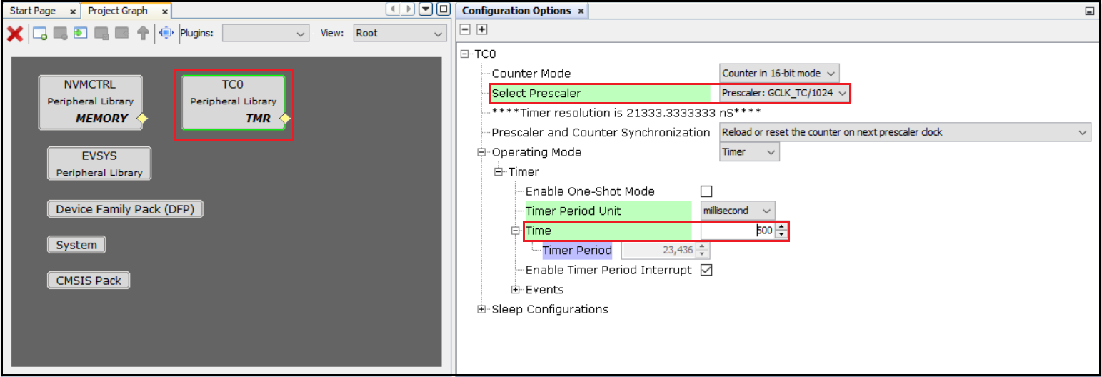
This will toggle the LED every 0.5 seconds, producing a LED blink every second.
-
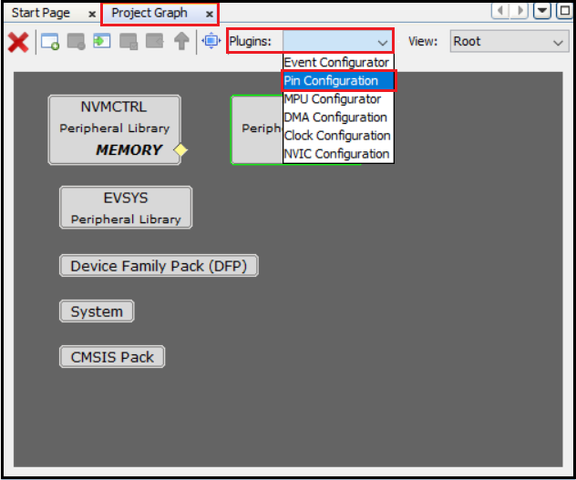
Launch the Pin Configuration manager by clicking Project Graph > Plugins > Pin Configuration.
-
Setup pin “PC05” as the board’s LED, set custom name as “LED” and Direction as “Out”:
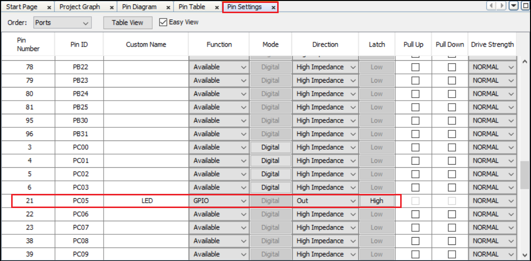
This is necessary because the project doesn’t use a Board Support Package (BSP).
-
Generate the application’s code for the first time.
-
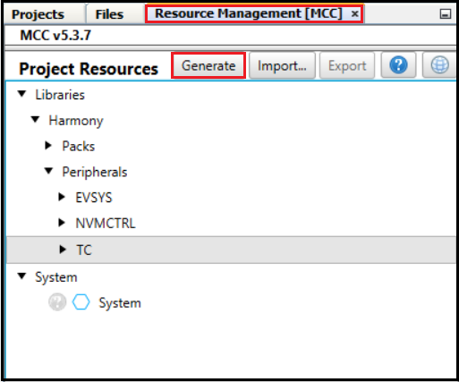
Generate the code by using MCC. From the left side tab, Resource Management [MCC], go to Project Resources and click on the Generate button.
- Note:
- You can open the Content Manager anytime and download/rebase the Harmony packages by clicking the Content Manager under the Device Resources tab as shown below.

- Note:
-
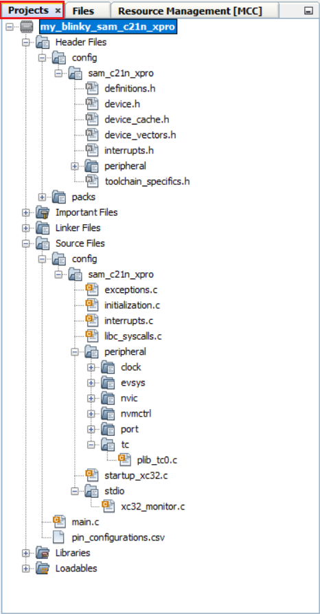
Let’s examine the software just created in the Projects panel of MPLAB® X IDE Header Files are shown on the top and Source Files are shown on the bottom.
Note: The icons used in this picture of the project’s organization make it seem like the files of the project are organized this way on disk. In fact, this is a virtual organization of these files, not an actual one. On disk, the source and header files are not separated. The following table describes the Header and Source files generated from the sample project:
# Source File Descriptions 1 definitions.h Provides configuration-specific definitions 2 exceptions.c Implements exception handlers 3 initialization.c Implements SYS_Initialize to initializes all libraries and applications 4 interrupts.c Implements the interrupt vectors 5 peripheral [libraries] Implements peripheral libraries used by the project 6 startup.c Startup code for the application If you click on the Projects tab you will see the actual organization of these files on your drive:
Adding Code to main.c
Double click on main.c to bring up an editor window and update it to obtain the following code:
static bool volatile bToggleLED = false;

// This function is called after period expires
void TC0_CH0_TimerInterruptHandler(TC_TIMER_STATUS status, uintptr_t context)
{
    bToggleLED = true;
}

// *****************************************************************************
// *****************************************************************************
// Section: Main Entry Point
// *****************************************************************************
// *****************************************************************************

int main ( void )
{
    // Initialize all modules
    SYS_Initialize(NULL);

    // Register callback function for CH0 period interrupt
    TC0_TimerCallbackRegister(TC0_CH0_TimerInterruptHandler, (uintptr_t)NULL);

    // Start the timer channel 0
    TC0_TimerStart();

    while ( true )
    {
        if ( bToggleLED )
        {
            bToggleLED = false;
            LED_Toggle();
        }
    }

    // Execution should not come here during normal operation
    return EXIT_FAILURE;
}
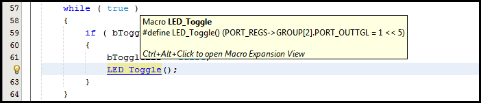
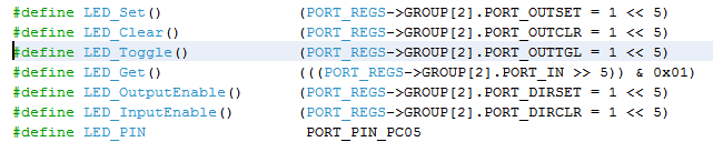
If you do a control click on “LED_Toggle()” the editor will bring up where this token is defined in the file plib_port.h:
Upload project to SAMC21N Xplained pro Evaluation Kit
-
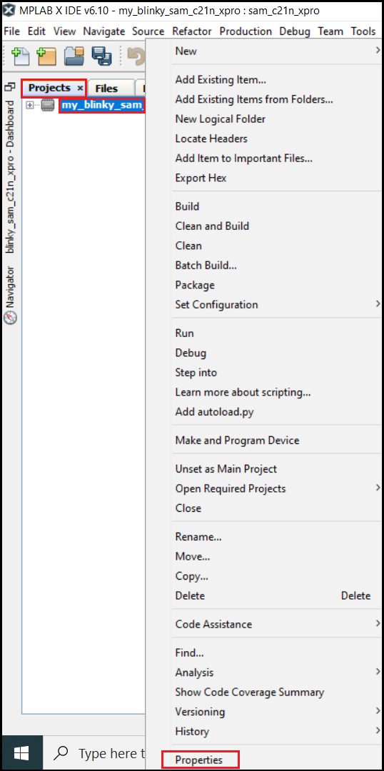
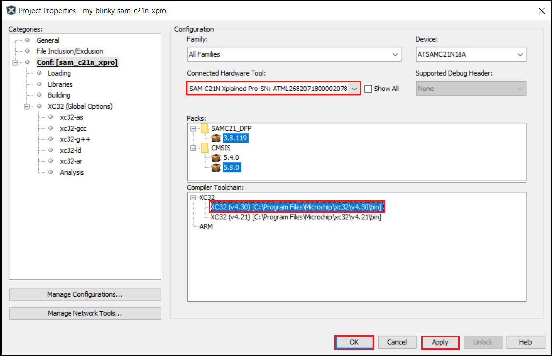
Do a right mouse click on the project’s name and bring up the Project Properties dialog:
-
Under Categories section, select Conf: (sam_c21n_xpro), and in the Configuration section, select the hardware tool and XC32 Compiler toolchain (here v4.40). Click Apply, and then click OK
-
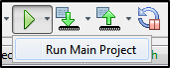
Build and run the project: The board’s LED should flash with a 1 second period
We have now implemented a heartbeat for future applications. The LED blinking indicates that the application hasn’t frozen or isn’t stuck in a while(1){} loop (e.g.: assert or exception).
Result
If configured correctly, the LED PC05 on the SAMC21N Xplained Pro Evaluation Kit should now flash ON/OFF at 500 ms intervals.
Note
This page has been verified with the following versions of software tools:
- MPLAB X IDE v6.20
- MPLAB XC32 Compiler v4.40
- MPLAB Code Configurator Plugin v5.5.1
- MPLAB Harmony v3 “csp” repo v3.18.5
Because Microchip regularly update tools, occasionally there could be minor differences with the newer versions of the tools.
References
- SAMC21N Xplained Pro Evaluation Kit User Guide and Datasheet
- MPLAB X IDE User’s Guide
- How to Set up the Tools Required to Get Started with MPLAB® Harmony v3 and MCC
- MPLAB Harmony 3 Content Manager