![]()
WDT timeout
This example application shows how to generate a Watchdog timer reset by emulating a deadlock.
Description
This example application shows how the WDT peripheral library resets the watchdog timer by not feeding the watchdog on switch press. The application sets up the watchdog to reset the device. The application also sets up the timer to blink an LED to emulate a process. A user switch press forces the device to wait in an infinite loop to emulate a deadlock. As a result a device reset is triggered as the watchdog counter overflows the bounded value.
Downloading and building the application
To clone or download this application from Github, go to the main page of this repository and then click Clone button to clone this repository or download as zip file. This content can also be downloaded using content manager by following these instructions.
Path of the application within the repository is apps/wdt/wdt_timeout/firmware .
To build the application, refer to the following table and open the project using its IDE.
| Project Name | Description |
|---|---|
| sam_9x60_curiosity.X | MPLABX project for SAM9X60 Curiosity Development Board |
Setting up AT91Bootstrap loader
To load the application binary onto the target device, we need to use at91bootstrap loader. Refer to the at91bootstrap loader documentation for details on how to configure, build and run bootstrap loader project and use it to bootstrap the application binaries.
Setting up the hardware
The following table shows the target hardware for the application projects.
| Project Name | Board |
|---|---|
| sam_9x60_curiosity.X | SAM9X60 Curiosity Development Board |
Setting up SAM9X60 Curiosity Development Board
Addtional hardware required
- SD Card with FAT32 file system
Setting up the SD Card
- Download harmony MPU bootstrap loader from this location
- Copy the downloaded boot loader binary( boot.bin) onto the SD card
Setting up the board
- SDMMC slot used for bootloading the application is SDMMC0 (J3)
- Connect the USB port J1 on board to the computer using a micro USB cable (to power the board).
- Connect a FTDI cable from J11 connector to computer.
Running the Application
- Build the application using its IDE
- Copy the output binary (named ‘harmony.bin’) onto the SD Card (Refer to the ‘Setting up hardware’ section above for setting up the SD card)
- Insert the SD card into SDMMC slot on the board (Refer to the ‘Setting up hardware’ section for the correct SDMMC slot)
- Open the Terminal application (Ex.:Tera term) on the computer.
- Connect to the Virtual COM port and configure the serial settings as follows:
- Baud : 115200
- Data : 8 Bits
- Parity : None
- Stop : 1 Bit
- Flow Control : None
- Reset the board to run the application
-
LED blinks in blue color and the console displays the following message
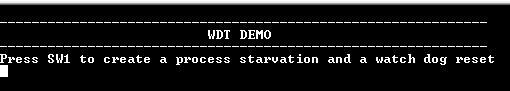
- Press the switch to put the system in a deadlock
-
LED toggles between green and blue color and console displays the following message
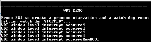
- WDT will reset the device in four seconds and the demonstration should restart
Following table provides details of switch and LED:
| Board | Switch Name | LED Name |
|---|---|---|
| SAM9X60 Curiosity Development Board | USER SW | RGB_LED(Blue, Green) |