![]()
PWM channels
This example demonstrates how to use the PWM peripheral to generate PWM signals.
Description
This example shows how to configure the PWM to generate PWM signals whose duty and period can be configured independently.
Downloading and building the application
To clone or download this application from Github, go to the main page of this repository and then click Clone button to clone this repository or download as zip file. This content can also be downloaded using content manager by following these instructions.
Path of the application within the repository is apps/pwm/pwm_channels/firmware .
To build the application, refer to the following table and open the project using its IDE.
| Project Name | Description |
|---|---|
| sam_9x60_curiosity.X | MPLABX project for SAM9X60 Curiosity Development Board |
Setting up AT91Bootstrap loader
To load the application binary onto the target device, we need to use at91bootstrap loader. Refer to the at91bootstrap loader documentation for details on how to configure, build and run bootstrap loader project and use it to bootstrap the application binaries.
Setting up the hardware
The following table shows the target hardware for the application projects.
| Project Name | Board |
|---|---|
| sam_9x60_curiosity.X | SAM9X60 Curiosity Development Board |
Setting up SAM9X60 Curiosity Development Board
- Connect a programming cable from JTAG connector J12 on board to programmer(J-32 Debugger).
- Connect programmer(J-32 Debugger) to computer using a micro USB cable.
- Connect the USB port J1 on board to the computer using a micro USB cable (to power the board).
- Conect the UART Debug port J11 to computer using a FTDI Cable.
- Connect PB11 (PIN 29 of Connector J9) to an an oscilloscope/Logic analyzer
- Connect PB12 (PIN 32 of Connector J9) to an an oscilloscope/Logic analyzer
- Connect PB13 (PIN 16 of Connector J8) to an an oscilloscope/Logic analyzer
Running the Application
- Open the Terminal application (Ex.:Tera term) on the computer.
- Connect to the USB Virtual COM port and configure the serial settings as follows:
- Baud : 115200
- Data : 8 Bits
- Parity : None
- Stop : 1 Bit
- Flow Control : None
- Build and program the application using its IDE
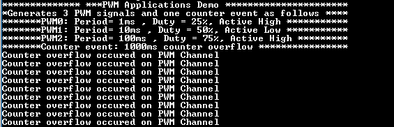
- PWM0 generates an active high PWM signal with 1 ms period and 25% duty on PB11 (PIN 29 of connector J9)
- PWM1 generates an active low PWM signal with 10 ms period and 50% duty on PB12 (PIN 32 of connector J9)
- PWM2 generates an active high PWM signal with 100ms period and 75% duty on PB13 (PIN 16 of connector J8)
-
Whenever a counter event occurs on PWM channel 4, console is upated as follows:
RGB_LED pulses with bluish white hue as all the three PWM signals are connected to the cathodes of the RGB LED