![]()
FLEXCOM USART interrupt
This example application shows how to use the flexcom module in USART mode.
Description
This application configures the flexcom peripheral in USART mode and performs read and write operation in a non-blocking manner. The peripheral interrupt is used to manage the transfer. It receives 10 characters from the terminal window and echoes them back.
Downloading and building the application
To clone or download this application from Github, go to the main page of this repository and then click Clone button to clone this repository or download as zip file. This content can also be downloaded using content manager by following these instructions.
Path of the application within the repository is apps/flexcom/flexcom_usart_echo_interrupt/firmware .
To build the application, refer to the following table and open the project using its IDE.
| Project Name | Description |
|---|---|
| sam_9x60_curiosity.X | MPLABX project for SAM9X60 Curiosity Development Board |
Setting up AT91Bootstrap loader
To load the application binary onto the target device, we need to use at91bootstrap loader. Refer to the at91bootstrap loader documentation for details on how to configure, build and run bootstrap loader project and use it to bootstrap the application binaries.
Setting up the hardware
The following table shows the target hardware for the application projects.
| Project Name | Board |
|---|---|
| sam_9x60_curiosity.X | SAM9X60 Curiosity Development Board |
Setting up SAM9X60 Curiosity Development Board
Addtional hardware required
Setting up the board
- Connect a programming cable from JTAG connector J12 on board to programmer(J-32 Debugger).
- Connect programmer(J-32 Debugger) to computer using a micro USB cable.
- Connect the USB port J1 on board to the computer using a micro USB cable (to power the board)
- Insert USB UART Click board into MIKROBUS Connector J8
Running the Application
- Open the Terminal application (Ex.:Tera term) on the computer.
- Connect to the USB Serial COM port and configure the serial settings as follows:
- Baud : 115200
- Data : 8 Bits
- Parity : None
- Stop : 1 Bit
- Flow Control : None
- Build and Program the application using its IDE.
-
The console displays the following message
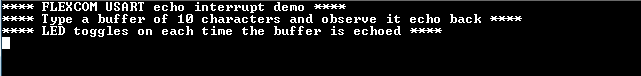
- Type a line of characters and press the Enter key (NOTE: Number of characters entered before pressing enter key must be less than 256))
- Entered line will be echoed back and the LED is toggled
Refer to the following table for LED name:
| Board | LED Name |
|---|---|
| SAM9X60 Curiosity Development Board | RGB_LED(Green) |