![]()
Low power modes
This example application shows how to enter low power modes of SAM9X60 MPU.
Description
The Clock system generates and distributes the clock for the processor and peripherals. This example application shows how device enters in the Idle mode and Ultra low power mode.
Downloading and building the application
To clone or download this application from Github, go to the main page of this repository and then click Clone button to clone this repository or download as zip file. This content can also be downloaded using content manager by following these instructions.
Path of the application within the repository is apps/clock/low_power/firmware .
To build the application, refer to the following table and open the project using its IDE.
| Project Name | Description |
|---|---|
| sam_9x60_curiosity.X | MPLABX project for SAM9X60 Curiosity Development Board |
Setting up AT91Bootstrap loader
To load the application binary onto the target device, we need to use at91bootstrap loader. Refer to the at91bootstrap loader documentation for details on how to configure, build and run bootstrap loader project and use it to bootstrap the application binaries.
Setting up the hardware
The following table shows the target hardware for the application projects.
| Project Name | Board |
|---|---|
| sam_9x60_curiosity.X | SAM9X60 Curiosity Development Board |
Setting up SAM9X60 Curiosity Development Board
- Connect a programming cable from JTAG connector J12 on board to programmer(J-32 Debugger).
- Connect programmer(J-32 Debugger) to computer using a micro USB cable.
- Connect the USB port J1 on each board to the computer using a micro USB cable (to power the board).
- Connect FTDI cables from J11 connector to computer in each board.
Running the Application
- Open the Terminal application (Ex.:Tera term) on the computer.
- Connect to the EDBG/Jlink Virtual COM port and configure the serial settings as follows:
- Baud : 115200
- Data : 8 Bits
- Parity : None
- Stop : 1 Bit
- Flow Control : None
- Build and program the application using its IDE
- LED toggles every 1 second
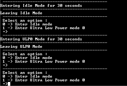
- Press ‘0’ in the terminal window
- Observe the message “Entering Idle Mode for 30 seconds” in the terminal window and LED stops toggling
- Wait for 30 seconds and observe the message “Leaving Idle Mode” in the terminal window and LED toggles every 1 second
- Press ‘1’ in the terminal window
- Observe the message “Entering ULP0 Mode for 30 seconds” in the terminal window and LED stops toggling
- Wait for 30 seconds and observe the message “Leaving ULP0 Mode” in the terminal window and LED toggles every 1 second
Refer to the following table for LED name:
| Board | LED Name |
|---|---|
| SAM9X60 Curiosity Development Board | RGB_LED(Blue) |