![]()
CAN blocking
This example application shows how to use the CAN module to transmit and receive CAN messages in polling mode.
Description
This application transmits CAN message to CAN Bus and receives CAN message from CAN Bus. To run this application, two evaluation boards of same type are required. These boards acts as different nodes on the CAN bus. Same application is programmed onto both the boards. Boards are connected to PC via UART. While running the application, user can send and receive CAN messages between the boards using UART console applications running on the PC.
Downloading and building the application
To clone or download this application from Github, go to the main page of this repository and then click Clone button to clone this repository or download as zip file. This content can also be downloaded using content manager by following these instructions.
Path of the application within the repository is apps/can/can_normal_operation_blocking/firmware .
To build the application, refer to the following table and open the project using its IDE.
| Project Name | Description |
|---|---|
| sam_9x60_curiosity.X | MPLABX project for SAM9X60 Curiosity Development Board |
Setting up AT91Bootstrap loader
To load the application binary onto the target device, we need to use at91bootstrap loader. Refer to the at91bootstrap loader documentation for details on how to configure, build and run bootstrap loader project and use it to bootstrap the application binaries.
Setting up the hardware
The following table shows the target hardware for the application projects.
| Project Name | Board |
|---|---|
| sam_9x60_curiosity.X | SAM9X60 Curiosity Development Board |
Setting up SAM9X60 Curiosity Development Board
-
Connect SAM9X60 Curiosity Development Board to another SAM9X60 Curiosity Development Board as per the pin connections shown below
SAM9X60-Curiosity - 1 SAM9X60-Curiosity - 2 CAN1_H, PIN 4 of J7 CAN1_H, PIN 4 of J7 CAN1_L, PIN 5 of J7 CAN1_L, PIN 5 of J7 GND, PIN 3 of J7 GND, PIN 3 of J7 - Connect a programming cable from JTAG connector J12 on board to programmer(J-32 Debugger).
- Connect programmer(J-32 Debugger) to computer using a micro USB cable.
- Connect the USB port J1 on each board to the computer using a micro USB cable (to power the board).
- Connect FTDI cables from J11 connector to computer in each board.
Running the Application
- Open the Terminal application (Ex.:Tera term) on the computer.
- Connect to the EDBG/Jlink Virtual COM ports associated with each board and configure the serial settings as follows:
- Baud : 115200
- Data : 8 Bits
- Parity : None
- Stop : 1 Bit
- Flow Control : None
- Build and program the application on both the boards using its IDE
- In the console associated with board 2, press “2” to receive a CAN message
- In the console associated with board 1, press “1” to transmit a CAN message
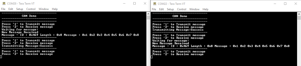
- Transmitted message description and status will be displayed in the console window of board 1
- Received message will be displayed in the console window of board 2
- If the steps are executed in this sequence, the final output in the consoles will be as below (console on the left is the transmitter (board 1) and the one on the right is receiver (board 2)):