
1.2.3.3 SAME70 Xplained Ultra
The following picture shows the SAME70 Xplained Ultra board connected with PL460-EK and REB215-XPRO expansion boards:

PL460-EK is connected to EXT1 connector (J602) of SAME70 Xplained Ultra. A 15V DC jack must be plugged into PL460-EK in order to supply the power for PLC transmission. Since the enclosure of PL460-EK does not fit with SAME70 Xplained Ultra, the user must be very careful if the PLC wire is connected to the mains because not all the board is isolated from mains (PLC signal). For more information about PL460-EK refer to its user guide.
REB215-XPRO is connected to EXT2 connector (J604) of SAME70 Xplained Ultra. For more information about REB215-XPRO refer to its user guide.
REB215-XPRO is only used in the PLC-RF Hybrid projects (see Table 1-2). In the PLC-RF Hybrid projects, it is possible to connect only one expansion board and the application runs correctly, with only PLC or RF PHY Tester Tool available.
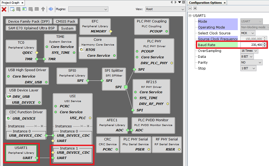
- Manage RF PHY Tester Tool . UART baud-rate is configured at 230400 bps.
- Flash/debug the SAME70 device with the on-board Microchip Embedded Debugger (EDBG)
- Manage PLC PHY Tester Tool . The baud-rate in the PC tool can be configured to any value because it is USB, not UART.
The serial interface used for PLC or RF PHY Tester Tool is configured in the user.h file (only for PLC-RF Hybrid projects) and in the MCC configuration of USI service:
#define USER_PLC_USI_INSTANCE_INDEX   SRV_USI_INDEX_0
#define USER_RF_USI_INSTANCE_INDEX    SRV_USI_INDEX_1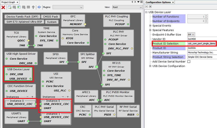
For more information about SAME70 Xplained Ultra refer to its user guide.