1.2.1 PLC PHY Tester Tool
The Power Line Communications (PLC) PHY Tester Tool has been developed to allow the user to test basic characteristics of PHY layers of Microchip PLC products. This tool is able to configure the different PHY layer parameters such as modulation schemes, transmission power, etc. and makes the interchange of basic PLC messages possible.
- Microchip PLC PHY Tester PC Tool. It allows the interchange of basic PLC messages. Installer and user guide can be found in the previous link.
- Microchip PLC PHY Tester Tool Python library. It is more flexible than PLC PHY Tester PC Tool and allows to develop customized Python scripts to perform different operations such as message transmission/reception, noise measurement and PHY PIB access. To obtain Python libraries and example scripts contact to the Microchip Smart Energy support team.
The PLC Performance Validation documentation explains the different tests that can be done with PLC PHY Tester Tool (PC tool and Python library).
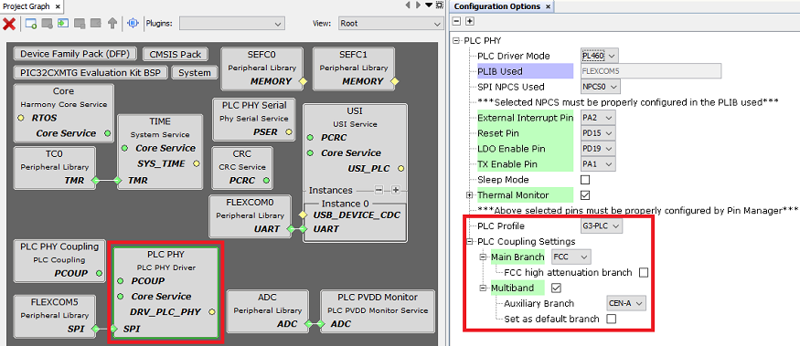
The PHY Tester Tool application loads by default the configuration to use the default transmission coupling stage of the evaluation kit (Multiband FCC + CENELEC-A for the PL460-EK). If other coupling configuration is required, it can be easily modified in the MCC options of PLC PHY driver, as shown below: