
1.2 PHY Tester Tool
The Physical (PHY) Layer Tester Tool has been developed to allow the user to test basic characteristics of PHY layers of Microchip PLC and RF products, and makes the interchange of basic PLC/RF messages possible.
There is a PLC-only application and a PLC-RF hybrid application. The hybrid application can use both PLC and RF PHY layers or only one of them. The following table shows the available PHY Tester Tool projects:
| PLC-only / PLC-RF Hybrid | Path | Boards |
|---|---|---|
| PLC-only | smartenergy_g3_apps\apps\phy_apps\phy_tester_tool\firmware\pic32cx_mtg_ek_pl460.X | PIC32CXMTG-EK + PL460-EK |
| PLC-only | smartenergy_g3_apps\apps\phy_apps\phy_tester_tool\firmware\pic32cx_mtsh_db_pl460.X | PIC32CXMTSH-DB + PL460-EK |
| PLC-only | smartenergy_g3_apps\apps\phy_apps\phy_tester_tool\firmware\sam_e70_xult_pl460.X | SAME70 Xplained Ultra + PL460-EK |
| PLC-only | smartenergy_g3_apps\apps\phy_apps\phy_tester_tool\firmware\wbz451_curiosity_pl460.X | WBZ451 Curiosity + PL460-EK |
| PLC-RF Hybrid | smartenergy_g3_apps\apps\phy_apps\phy_tester_tool_hybrid\firmware\pic32cx_mtg_ek_pl460_rf215.X | PIC32CXMTG-EK + PL460-EK + REB215-XPRO |
| PLC-RF Hybrid | smartenergy_g3_apps\apps\phy_apps\phy_tester_tool_hybrid\firmware\sam_e70_xult_pl460_rf215.X | SAME70 Xplained Ultra + PL460-EK + REB215-XPRO |
It should be kept in mind that in order to obtain repeatable results, a PHY test must be done under controlled condition. It is recommended to carry out the test in an isolated path, free of other PLC/RF messages or interferences that can introduce uncontrolled signals in the channel to be evaluated.
The following figure shows the MCC project graph of Hybrid PHY Tester Tool application for PIC32CXMTG-EK:
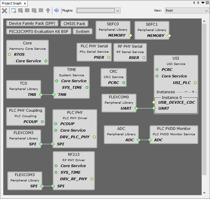
- Since it is an hybrid application, both PLC PHY and RF215 drivers are present. In the PLC-only application, the RF215 driver is not present.
- The PLC PVDD Monitor service is needed to monitor the PVDD voltage of PL460 in order to disable PLC transmission in case the voltage is not in the expected range, to avoid PL460 damage. If the PVDD voltage is in the expected range the PLC transmission is enabled.
- The PLC PHY Coupling service is needed to configure the PLC transmission parameters for the selected transmission coupling branch.
- The USI, PLC PHY Serial and RF PHY Serial services are needed to send/receive messages through serial interface (UART/USB) to/from PC tool.
- The Time system service is required by both PLC PHY and RF215 drivers. It is also used to blink periodically the status LED.