1.4.1.1 Basic Memory layout for CORTEX-M based MCUs
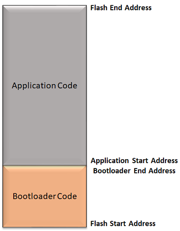
The placement of the Bootloader and the application in flash memory should be such that the application will not overwrite the Bootloader, and the Bootloader can properly program the application when it is downloaded.
Bootloader code is always placed at start of the flash address
CORTEX-M Devices where both Boot Flash Memory (BFM) and Program Flash Memory (PFM) are available, The bootloader is placed in Boot Flash Memory (BFM) or Program Flash Memory (PFM) based on the size of the bootloader and available Boot flash memory on the device.
If the bootloader fits into the available BFM, it is placed in BFM. The user application can use the complete area of the program Flash memory.
If the bootloader does not fit into the available BFM, It is placed in PFM. The user application can use the remaining area of the program Flash memory.
Note: The Boot Flash and Program Flash memory end addresses may vary from device to device. Refer to respective Data sheets for details of Flash memory layout.
The application code can be placed anywhere after the bootloader end address. The application start address should be aligned to Erase Unit Size of the device
As the Bootloader code requires the application start address to be mentioned at compile time, it should match in both the application and bootloader
Note:
The start address and the end address of the Bootloader and the application will vary for different devices. Refer to respective Data sheets for details of Flash memory layout.
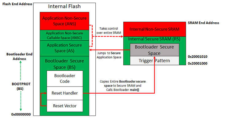
Memory layout for TrustZone devices
The Bootloader is part of the Secure Flash BOOTPROT region with configurable BNSC region
The Bootloader will always jump to the application Secure Region at specified application start address after programming. Therefore, The applications reset handler should be part of the application Secure Region, which can further call its Non-Secure region if any.
The Bootloader will not be using the initial 4KB of SRAM as it will be cleared by the BOOTROM at reset. Therefore, the bootloader trigger pattern has to be stored at 0x20001000 of the SRAM.
Note
The proper fuse settings required by the application (Example: AS, ANSC, RS, ...) have to be sent along with application binary during programming to bootloader using the Device configuration command