1.5.2 MCC Project Configuration
The following figure shows the MCC project graph of MAC-RT PLC & Go application for PIC32CXMTG-EK:
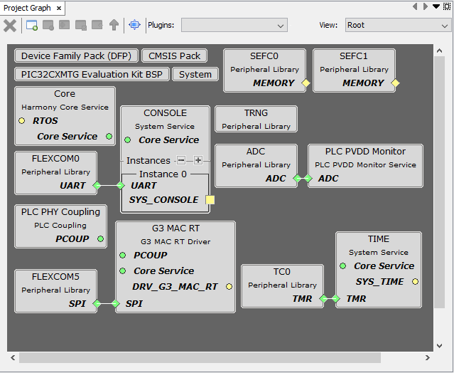
- The G3 MAC RT driver is needed to manage the G3-PLC MAC-RT layer running on the PLC device and transmit/receive PLC frames.
- The PLC PVDD Monitor service is needed to monitor the PVDD voltage of PL460 in order to disable PLC transmission in case the voltage is not in the expected range, to avoid PL460 damage. If the PVDD voltage is in the expected range the PLC transmission is enabled.
- The PLC PHY Coupling service is needed to configure the PLC transmission parameters for the selected transmission coupling branch.
- The Console system service is needed to manage the serial interface console.
- The Time system service is required by the G3 MAC RT driver. It is also used to blink periodically the status LED.
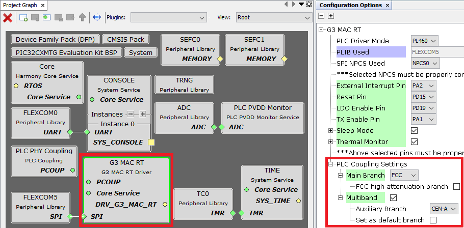
The MAC-RT PLC & Go application loads by default the configuration to use the default transmission coupling stage of the evaluation kit (Multiband FCC + CENELEC-A for the PL460-EK). If other coupling configuration is required, it can be easily modified in the MCC options of G3 MAC RT driver, as shown below:
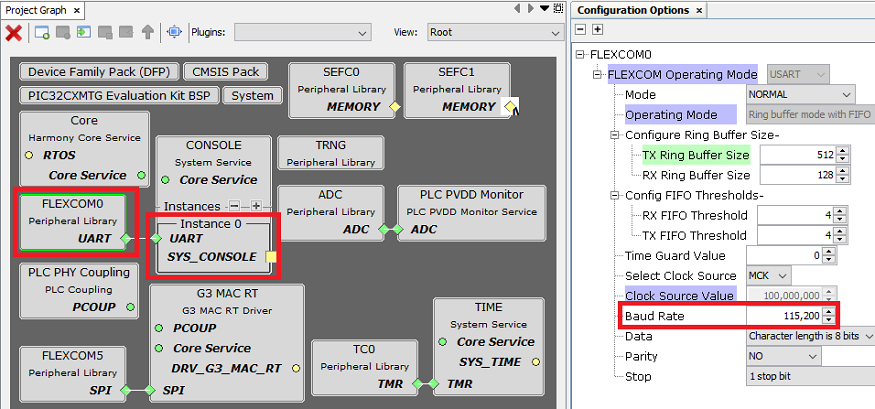
The serial interface used for the MAC-RT PLC & Go console is configured in the MCC configuration of Console service. It can be UART or USB (if the device supports USB).