1.1.1 MCC Project Configuration
The following figure shows the MCC project graph of Hybrid PHY Sniffer Tool application for PIC32CXMTG-EK:
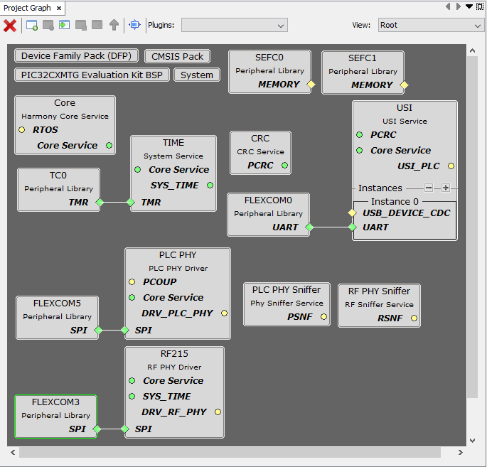
- Since it is an hybrid application, both PLC PHY and RF215 drivers are present. In the PLC-only application, the RF215 driver is not present.
- The USI, PLC PHY Sniffer and RF PHY Sniffer services are needed to send/receive messages through serial interface (UART/USB) to/from PC tool.
- The Time system service is required by both PLC PHY and RF215 drivers. It is also used to blink periodically the status LED.
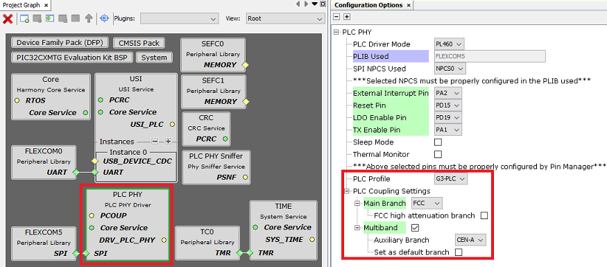
The PHY Sniffer Tool application loads by default the configuration to use the default coupling stage of the evaluation kit (Multiband FCC + CENELEC-A for the PL460-EK). If other PLC band configuration is required, it can be easily modified in the MCC options of PLC PHY driver, as shown below:
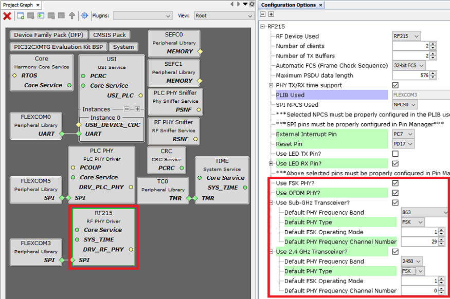
The Hybrid PHY Sniffer Tool application is configured by default with the default RF configuration defined by G3-Hybrid (863 MHz band, channel number 29 and FSK operating mode 1). If other RF configuration is required, it can be easily modified in the MCC options of RF215 driver, as shown below:
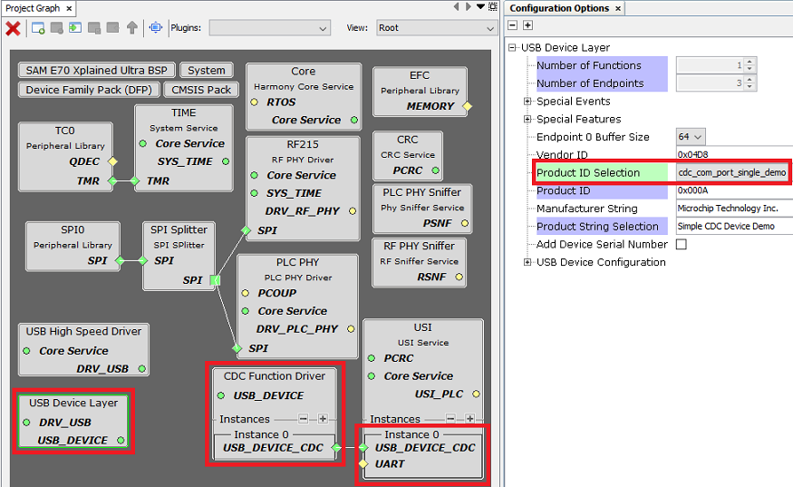
The serial interface used for PHY Sniffer Tool is configured in the MCC configuration of USI service. It can be UART or USB (if the device supports USB).