
1.10.3.1 PIC32CXMTG-EK
The following picture shows the PIC32CXMTSH-DB board connected with PL460-EK and REB215-XPRO expansion boards:

PL460-EK is connected to XPLAINED PRO connector (J20) of PIC32CXMTSH-DB. A 15V DC jack must be plugged into PL460-EK in order to supply the power for PLC transmission. For more information about PL460-EK refer to its user guide.
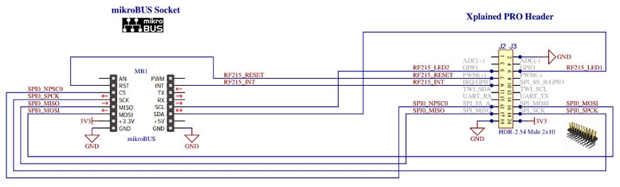
REB215-XPRO is connected to mikroBUS 1 connector (J8) of PIC32CXMTG-EK using a mikroBUS to REB215 adapter (schematic shown below). For more information about REB215-XPRO refer to its user guide.
Since the enclosure of PIC32CXMTSH-DB cannot be closed when REB215-XPRO is connected, the user must be very careful if the PLC wire or voltage/current sensors are connected to the mains because not all the board is isolated from mains.
It is possible to connect only one expansion board and the application runs correctly, with only PLC or RF interface available.
- Manage Metering Demo console. UART baud-rate is configured at 115200 bps.
- Flash/debug the PIC32CXMTSH device with an external debugger.
A 12V DC jack must be plugged into PIC32CXMTSH-DB in order to supply the power of the board.
For more information about PIC32CXMTSH-DB refer to its user guide. There is also more information in the Metering Demo documentation (smartenergy repository).