
1.2.1.3 Configuring The Library
PLC PHY Coupling Service can be configured via MCC.
Alternatevely, the generated source/header files can be modified for custom configuration.
Configuring via MCC
The following snapshots show the MCC configuration window for PLC PHY Coupling Service and brief description.
The configuration options will vary depending on the PLC protocol used by the PLC Driver (G3 or PRIME).
The configuration dynamic values (purple colour) will be updated, depending on PLC Driver Mode and PLC Coupling Settings in PLC Driver MCC configuration, in order to apply the configuration/calibration values for Evaluation Kits and/or reference designs.
G3 Configuration Options
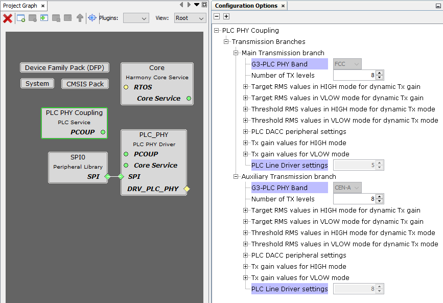
Transmission Branches:
Available only if G3 selected as PLC Profile in PLC PHY Driver MCC configuration, or G3 MAC RT Driver used
Main Transmission branch:
PLC PHY Coupling configuration for Main Transmission branch
Auxiliary Transmission branch:
PLC PHY Coupling configuration for Auxiliary Transmission branch
Available only if Multiband enabled in PLC Driver MCC configuration
Each transmission branch is configured inependentely. In addition to Common Configuration Options, the following options are available for each transmission branch:
G3-PLC PHY Band:
Indicates the frequency band associated to the corresponding transmission branch, as selected in PLC Driver MCC configuration
PLC DACC peripheral settings:
PLC Device's DACC peripheral register values (PHY PIB PLC_ID_DACC_TABLE_CFG)
These values should not be modified by the user
PRIME Configuration Options
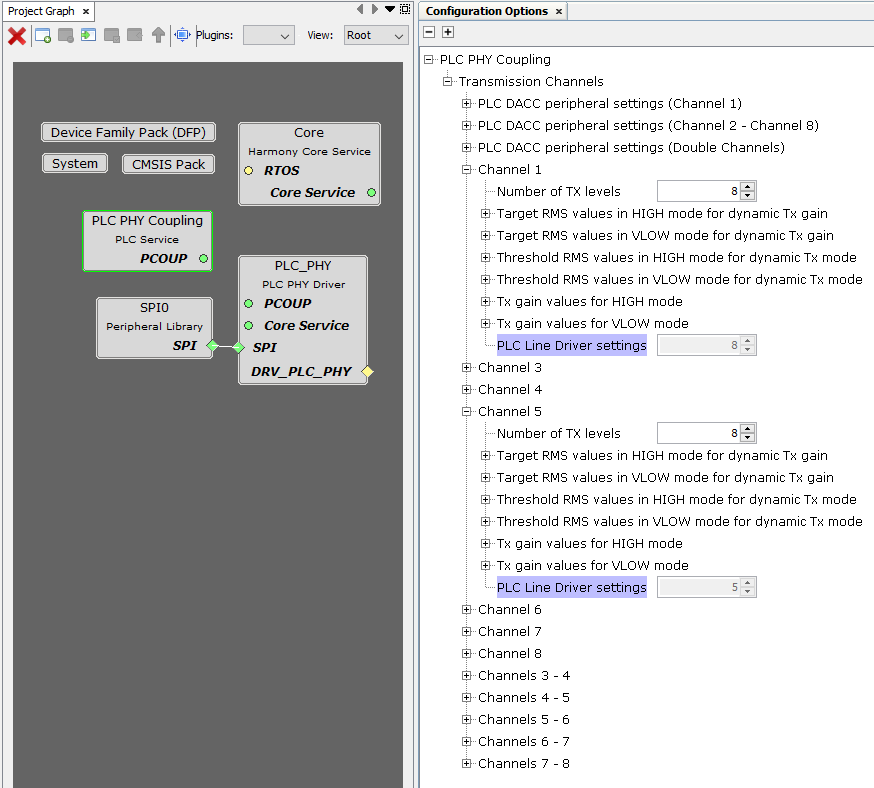
Transmission Channels:
Available only if PRIME is selected as PLC Profile in PLC PHY Driver
PLC DACC peripheral settings (Channel 1):
PLC DACC peripheral settings (Channel 2 - Channel 8):
PLC DACC peripheral settings (Double Channel):
PLC Device's DACC peripheral register values (PHY PIB PLC_ID_DACC_TABLE_CFG) for single channel 1 / single channels 2 to 8 / double channels
These values should not be modified by the user
Channel "i":
PLC PHY Coupling configuration for single channel "i"
Available only if Channel "i" is enabled in PLC PHY Driver MCC configuration
Channels "i - j":
PLC PHY Coupling configuration for double channel "i - j" (two consecutive channels)
Available only if Channels "i - j" is enabled in PLC PHY Driver MCC configuration
Each channel is configured inependentely. Common Configuration Options are available for each enabled channel.
Common Configuration Options
Number of TX levels:
PHY PIB: PLC_ID_NUM_TX_LEVELS
Number of transmission attenuation levels supporting dynamic capabilities
G3: transmission attenuation levels in 3 dB steps
PRIME: transmission attenuation levels in 1 dB steps
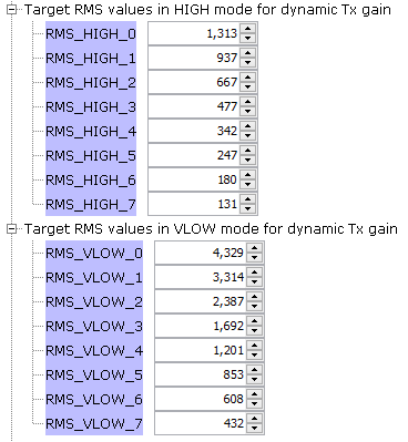
Target RMS values in HIGH mode for dynamic Tx gain:
PHY PIB: PLC_ID_MAX_RMS_TABLE_HI
RMS_HIGH_x:
Target RMS values in HIGH Tx mode for transmission attenuation level "x"
Target RMS values in VLOW mode for dynamic Tx gain:
PHY PIB: PLC_ID_MAX_RMS_TABLE_VLO
RMS_VLOW_x:
Target RMS values in VLOW Tx mode for transmission attenuation level "x"
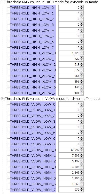
Threshold RMS values in HIGH mode for dynamic Tx mode:
PHY PIB: PLC_ID_THRESHOLDS_TABLE_HI
THRESHOLD_HIGH_LOW_x:
Threshold RMS values to update Tx mode from HIGH to LOW for transmission attenuation level "x"
Set to 0 to disable
THRESHOLD_HIGH_VLOW_x:
Threshold values to update Tx mode from HIGH to VLOW for transmission attenuation level "x"
Set to 0 to disable
Threshold RMS values in VLOW mode for dynamic Tx mode:
PHY PIB: PLC_ID_THRESHOLDS_TABLE_VLO
THRESHOLD_VLOW_LOW_x:
Threshold values to update Tx mode from VLOW to LOW for transmission attenuation level "x"
Set to 0 to disable
THRESHOLD_VLOW_HIGH_x:
Threshold values to update Tx mode from VLOW to HIGH for transmission attenuation level "x"
Set to maximum value to disable
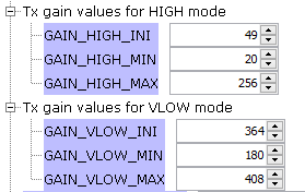
Tx gain values for HIGH mode:
PHY PIB: PLC_ID_GAIN_TABLE_HI
GAIN_HIGH_INI:
GAIN_HIGH_MIN:
GAIN_HIGH_MAX:
Initial/minimum/maximum transmission digital gain value for HIGH Tx mode
Set all to same value to disable dynamic Tx gain for HIGH Tx mode
Tx gain values for VLOW mode:
PHY PIB: PLC_ID_GAIN_TABLE_VLO
GAIN_VLOW_INI:
GAIN_VLOW_MIN:
GAIN_VLOW_MAX:
Initial/minimum/maximum transmission digital gain value for VLOW Tx mode
Set all to same value to disable dynamic Tx gain for VLOW Tx mode
PLC Line Driver settings:
PHY PIB: PLC_ID_IC_DRIVER_CFG
PLC Device and branch configuration. One value for PL360, three values for PL460:
0: PL360
5: PL460 using Main Transmission Branch with a single external filter. When transmitting, both ASO pins are activated simultaneously
7: PL460 using Main Transmission Branch with two external filters. When transmitting, ASO0 is activated for HIGH Tx mode, while ASO1 is activated for LOW/VLOW Tx modes
8: PL460 using Auxiliary Transmission Branch
Modifying Generated Source Code
PLC PHY Coupling Service generates the srv_pcoup.c and srv_pcoup.h files. In the header file there are definition macros with the values configured via MCC.
The user can modify these files instead of using MCC interface.
In the current version, this is the only method to customize Tx Equalization values (not supported in MCC configuration window for PLC PHY Coupling Service).