1.1.1.3 Configuring The Library
PLC PHY Driver Specific User Configurations
PLC PHY Driver library should be configured via MCC. Below is the snapshot of the MCC configuration window for PLC PHY driver and brief description.
PLC Driver Mode:
Specifies the PLC device physically connected (PL360 or PL460).
The pins in use will vary depending on the device selected.
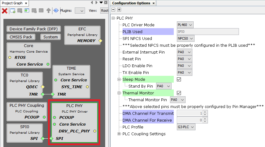
Configuration for PL460 device:
Figure . PL460 configuration options 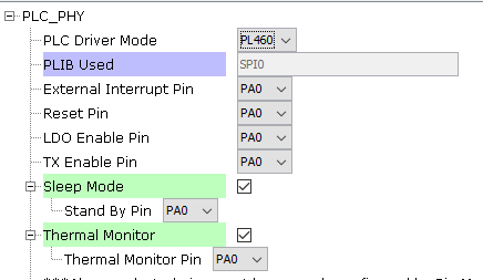
Configuration for PL360 device:
Figure . PL360 configuration options 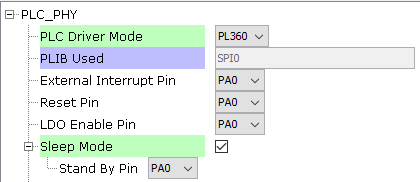
PLIB Used:
Indicates the SPI peripheral instance used by the PLC PHY driver.
The name of the peripheral will vary from device to device.
SPI NPCS Used:
SPI chip select line to be used by the PLC PHY driver.
It is only visible if the connected peripheral supports multiple chip select lines.
External Interrupt Pin:
GPIO pin to be used as external interrupt interface (active low).
This pin automatically indicates that the firmware running in the PLC device has one or more pending events to be consulted.
This pin must be configured as GPIO input in "Pin Settings" configuration. Set Pull Down and Low Level Interrupt configuration:
Figure . PLC PIO Interrupt settings 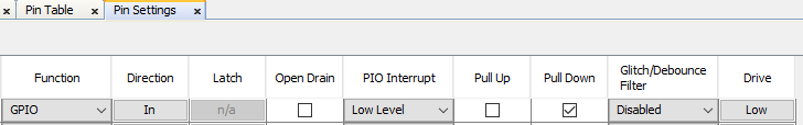
Reset Pin:
GPIO pin to be used as reset (active low).
This pin resets the core and the peripherals of the PLC device.
This pin must be configured as GPIO output in "Pin Settings" configuration.
LDO Enable Pin:
GPIO pin to be used as LDO enable (active high).
This pin provides power to the core voltage regulator embedded in the PLC device.
This pin must be configured as GPIO output in "Pin Settings" configuration.
TX Enable Pin:
GPIO pin to allow PLC transmissions (active high).
This pin must be configured as GPIO output in "Pin Settings" configuration.
It is only visible if PLC Driver Mode is configured as PL460.
Sleep Mode:
Enables the Sleep mode. In Sleep mode, the core and peripherals of the PLC device are reset, reducing power consumption.
Standby Pin:
GPIO pin to be used as sleep mode enable (active high).
This pin must be configured as GPIO output in "Pin Settings" configuration.
It is only visible if Sleep Mode is enabled.
Thermal Monitor:
Enables Thermal Monitor. It allows to check the Thermal Monitor pin of PL460 and not allow transmissions if Thermal Warning is indicated.
It is only visible if PLC Driver Mode is configured as PL460.
Thermal Monitor Pin (PL460 mode):
GPIO pin to check the status of the Thermal Monitor.
This pin must be configured as GPIO input in "Pin Settings" configuration. Set Pull Up configuration.
It is only visible if Thermal Monitor is enabled.
PLC Profile:
This option is used to select the PLC standard to comply with such as G3-PLC (ITU G.9903) or PRIME (ITU G.9904).
PLC Coupling Settings:
PLC Driver mode must have been selected before to obtain a valid PLC coupling settings for each mode.
Used to establish the hardware configuration associated to the PLC frequency bands to use.
The options of this configuration will vary from the selected PLC profile.
G3 profile:
The configuration will vary depending on the PLC Driver Mode selected.
PL460:
- Main Branch:
Figure . PL460: Hardware blocks in a single band 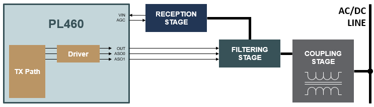
The main transmission branch uses the embedded class-D PLC line driver to optimize performance in terms of efficiency and EMC compliance, while reducing BOM cost and PCB complexity.
- This is the default branch for single-band applications either in CENELEC-A, CENELEC-B or FCC bands.
Figure . G3 frequency table 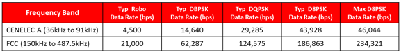
FCC high attenuation branch:
This option is visible only for FCC configured as the main branch.
The PL460 is capable of automatically managing two external filters in the filtering stage, each filter associated to an ASOx line.
- Multiband:
Figure . PL460: Hardware blocks in multiband 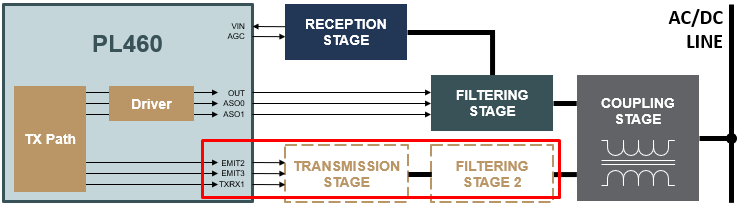
This option is visible only for FCC as main branch.
Used to select CENELEC-A or CENELEC-B as the auxiliary PLC PHY band.
Auxiliary Branch:
The Auxiliary Transmission Branch can provide an additional output bit-stream, if required.
The Auxiliary Transmission path cannot use the embedded PLC driver in the PL460 and requires an external circuit for signal amplification, in addition to the standard filtering and coupling stages.
Set as default branch:
Used to establish auxiliary branch in the intialization of the PHY PLC driver.
PL360:
- Main Branch:
Figure . PL360: Hardware blocks in a single band with external coupling 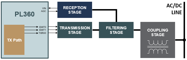
This is the default branch for single-band applications either in CENELEC-A, CENELEC-B or FCC bands.
Internal Driver:
- This option is visible only for PL360 driver mode, G3 profile and CENELEC-B configured as the main branch
Figure . PL360: Hardware blocks in a single band with internal coupling 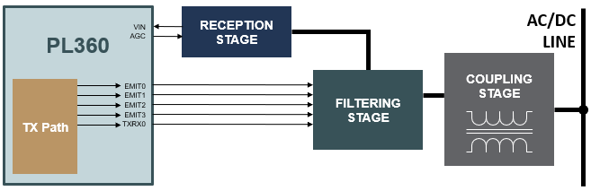
In case of using a coupling with internal driver, only one branch is allowed and all the four EMIT pins must be connected to the same point and transmission control is indicated by TXRX0.
- Multiband:
Figure . PL360: Hardware blocks in multiband with external coupling 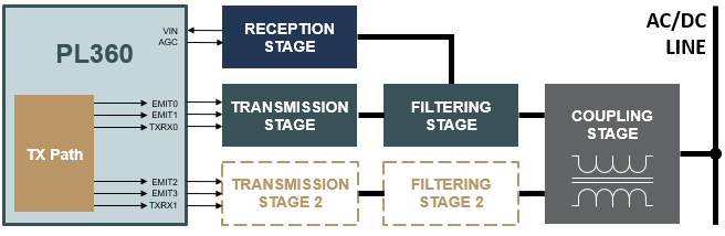
This option is visible only for FCC as main branch.
Used to select CEN-A or CEN-B as the auxiliary PLC phy band
Auxiliary Branch:
The Auxiliary Transmission Branch can provide an additional output bit-stream, if required.
Set as default branch:
Used to establish Auxiliary branch in the intialization of the PHY PLC driver.
- PRIME profile:
Figure . PRIME Frequency channels 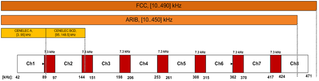
PHY PLC driver can handle several communications channels, the user can configure which set of channels the PLC device is allowed to operate on.
Single Channel
PLC frames will be transmitted and received using 1-channel frequency range.
Channel "i"
Enable Channel "i" to be used for a PLC frame.
Hardware configuration will vary depending on the selected configuration
- Channel 1 using the main branch
Figure . Configuration for single channel using the main branch 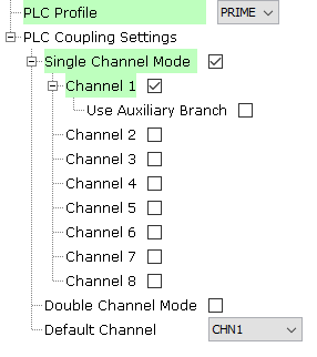
- Channel from 3 to 8 using the main branch
Figure . Configuration for single channel using channels 8, 5 and 3 via the main branch 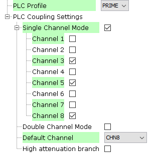
- Multiband using the auxiliary branch
Figure . Configuration for multiband using channels 8, 5 and 3 via the main branch and channel 1 via the auxiliary branch 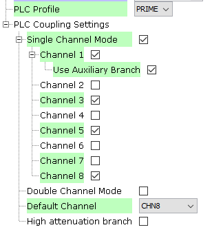
Double Channel
PLC frames will be transmitted and received using 2-channel frequency range.
Channel "i - j"
Enable Channels "i" and "j" to be used for a PLC frame.
- This mode is only available for using the main branch.
Figure . Configuration for double channel using channels 5-6 and channels 7-8 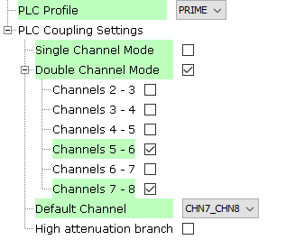
Default Channel
Used to establish the channel by default in which the PLC Driver is configured to transmit and receive.
High attenuation branch
This option is visible only for PL460 and it takes effect in the main branch.
The PL460 is capable of automatically managing two external filters in the filtering stage, each filter associated to an ASOx line.
RTOS Settings
Stack Size (in bytes):
Specifies the number of bytes to be allocated on the stack for the driver task.
Task Priority:
Specifies priority for the driver task thread. The value can vary based on RTOS used.
NVIC Configurations (Interrupt Priorities)
The PLC PHY driver has a strong dependency with a delay function implemented in the HAL module. This delay function is called from the interrupt handler associated with the External Interrupt pin.
In the Microchip implementation, the delay function uses the Time system service, which uses a timer peripheral. The timer interrupt priority must be higher (lower value) than the interrupt priority associated with the External Interrupt pin in order to ensure the correct operation.
For MCUs that does not have DMA (PIC32CXMT for example), the SPI interrupt priority must be higher (lower value) than the interrupt priority associated with the External Interrupt pin in order to ensure the correct operation.
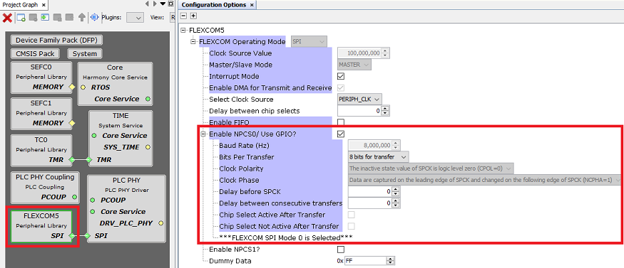
SPI Peripheral Configuration
For correct operation it is important that the SPI is properly configured in MCC. If the used peripheral supports multiple chip select lines, the corresponding NPCS has to be enabled and configured.
The maximum SPI clock frequency allowed depends on the PLC protocol and band used:
G3-PLC:
8 MHz if CENELEC-A or CENELEC-B band is used.
12 MHz if only FCC band is used.
PRIME:
8 MHz if Single Channel 1 used.
12 MHz if Sinche Channel 1 is not used.
When SPI dependency of PLC PHY driver is connected to a peripheral with SPI capability, some SPI options are automatically configured. The SPI clock frequency is configured to 8 MHz by default. There is not any requirement in terms of low SPI baudrate, the user can reduce it if needed. However, it is recommended to configure it as high as possible because the lower the SPI baudrate, the slower the response time. The other SPI configuration options should not be changed.
The following snapshot shows an example of valid SPI configuration for a PIC32CXMT device: