
1.2.1.1 How the Library Works
The PLC Physical Layer (PHY) implements some transmission capabilities with the following purposes:
Comply with regulatory requirements
Meet power injection and signal quality requirements
Compensate nonlinearities of the power supply and coupling harware designs, related to components' tolerances and PCB layout
Support different PLC devices (PL360/PL460) and transmission coupling harware designs
These capabilities are configured through PHY parameters (PIBs). The PLC PHY Coupling service offers a simple interface to set these PIBs, whose values can be configured via MCC.
The default PLC PHY Coupling configuration values are optimized for the Evaluation Kits, calibrated for each transmission coupling harware reference design and working band.
For custom designs different from the Microchip reference designs, it is recommended to recalibrate the PLC PHY Coupling configuration values. To help in this calibration process of the PLC PHY, Microchip provides the PHY Calibration Tool, an open source application developed with Python®. For further information, contact with the Smart Energy support team or refer to the PL360 Physical Calibration user guide.
PLC PHY Transmission Capabilities
Transmission capabilities implemented in the PLC PHY:
Transmission Modes
Equalization
Dynamic adaptation
Transmission Modes
Three transmission modes are available in the PLC PHY (PIB PLC_ID_CFG_IMPEDANCE):
| Tx Mode | PLC_ID_CFG_IMPEDANCE value | Description |
|---|---|---|
| HIGH | 0 | Optimized for high impedance (typically Z > 20 Ω) |
| LOW | 1 | Optimized for low impedance. In the current implementations this mode is not used |
| VLOW | 2 | Optimized for very low impedance (typically Z < 10 Ω) |
Transmission digital gain and equalization are independentely configured for each Tx mode. Since each Tx mode is optimized for an impedance range, the PLC PHY is also capable of selecting automatically the Tx mode, based on the estimated load impedance. This allows to achieve a good tradeoff between transmission performance, efficiency, signal quality and spectrum ripple for a wider range of load impedances.
Equalization
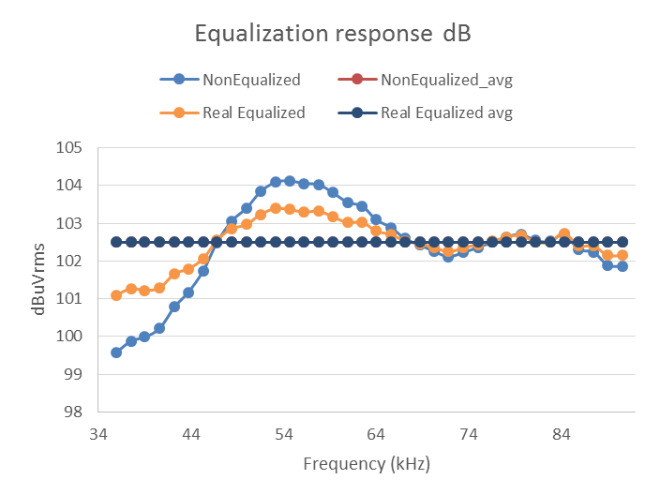
Usually, the transmitted signal has a non-flat frequency spectrum inside the working band (ripple), because of the frequency response of the external analog filter (discrete components). This ripple can be reduced by equalizing the transmitted signal.
The PLC PHY can perform this equalization by means of digital signal pre-distortion. A specific gain factor is assigned to each carrier in the working band, compensating the frequency response of the external analog filter. For different equalization configurations, the average signal level in the whole working band is maintained (pre-distorsion gain reduction is compensated).
The external analog filter may have different frequency response for different load impedances. For that reason, equalization is independentely configured for each Tx mode.
The following figure shows an example of equalization in the G3-PLC CENELEC-A band. It shows how the ripple is reduced after equalization, keeping the same signal average in band (overlapped curves).
Dynamic adaptation
The PLC PHY can modify the Tx mode and digital gain, dynamically after each transmission. Three automatic modes are available (PIB PLC_ID_CFG_AUTODETECT_IMPEDANCE):
| Auto Mode | PLC_ID_CFG_AUTODETECT_IMPEDANCE value | Tx Mode | Tx Gain |
|---|---|---|---|
| OFF | 0 | Fixed | Fixed |
| ON | 1 | Dynamic | Dynamic |
| AGC | 2 | Fixed | Dynamic |
The PLC Device receives its own transmitted signal and the RMS value is computed by the PHY (rmsCalc in DRV_PLC_PHY_TRANSMISSION_CFM_OBJ). This allows to estimate the load impedance and adjust the Tx mode/gain for the next transmission.
For dynamic Tx gain, a target RMS is configured and the digital Tx gain is adjusted (between configurable minumum and maximum) after each transmission. The objective is to try to inject the same signal level for different load impedances. For lower load impedances the Tx gain will be increased to inject the required signal level, while for higher load impedances the Tx gain will be reduced to reduce power consumption.
For dynamic Tx mode, RMS thresholds are configured to switch from one Tx mode to another. The objective is to try to use the most efficient Tx mode depending on the load impedance. The thresholds should be configured using an hystheresis window to avoid undesirable behaviours.
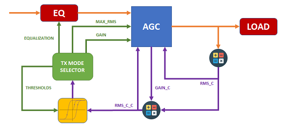
The following figure illustrates the interaction between the different functionalities described above:
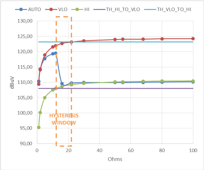
The following figure shows an example of the injected signal level in terms of the load impedance (from 0 to 100 Ω), for Auto Mode OFF (HIGH/VLOW modes) and ON:
PLC PHY Coupling parameters
The following table sumarizes the PLC PHY PIBs related to transmission configuration, coupling hardware design and PLC device used:
| PHY PIB | Description |
|---|---|
| PLC_ID_CFG_IMPEDANCE | Tx Mode |
| PLC_ID_CFG_AUTODETECT_IMPEDANCE | Auto Tx Mode. Enable/disable dynamic Tx mode/gain |
| PLC_ID_PREDIST_COEF_TABLE_HI | Pre-distorsion table for equalization in HIGH mode |
| PLC_ID_PREDIST_COEF_TABLE_VLO | Pre-distorsion table for equalization in VLOW mode |
| PLC_ID_PREDIST_COEF_TABLE_HI_2 | Pre-distorsion table for equalization in HIGH mode (only for PRIME Double Channel) |
| PLC_ID_PREDIST_COEF_TABLE_VLO_2 | Pre-distorsion table for equalization in VLOW mode (only for PRIME Double Channel) |
| PLC_ID_GAIN_TABLE_HI | Digital gain configuration for HIGH mode |
| PLC_ID_GAIN_TABLE_VLO | Digital gain configuration for VLOW mode |
| PLC_ID_CURRENT_GAIN | Indicates the digital gain for the next/current transmission. It may vary between transmissions if dynamic Tx gain is enabled |
| PLC_ID_CORRECTED_RMS_CALC | Indicates the RMS value of the last transmission, compensated with the dynamic Tx gain factor applied. This is the value used in dynamic adaptation algorithms |
| PLC_ID_NUM_TX_LEVELS | Number of transmission attenuation levels (attenuation field in DRV_PLC_PHY_TRANSMISSION_OBJ) supporting dynamic mode/gain |
| PLC_ID_MAX_RMS_TABLE_HI | Target RMS values in HIGH mode for dynamic Tx gain |
| PLC_ID_MAX_RMS_TABLE_VLO | Target RMS values in VLOW mode for dynamic Tx gain |
| PLC_ID_THRESHOLDS_TABLE_HI | Threshold RMS values in HIGH mode for dynamic Tx mode |
| PLC_ID_THRESHOLDS_TABLE_VLO | Threshold RMS values in VLOW mode for dynamic Tx mode |
| PLC_ID_IC_DRIVER_CFG | PLC Device (PL360/PL460) and branch configuration |
| PLC_ID_DACC_TABLE_CFG | PLC Device's DACC peripheral register values |