1.1 TCP/IP Berkeley TCP Client
The Berkeley TCP Client configuration demonstrates creating a network client with the Berkeley API to make a TCP/IP connection to a web server.
Description
The TCP/IP Berkeley TCP Client application is based on MPLAB® Harmony 3 TCP/IP Stack.
The Harmony TCP/IP stack is a collection of different network protocols.
The source files of Harmony 3 TCP/IP stack is available here.
The demo is created with MPLAB X IDE and MCC plugin.
MCC Project Graph - TCP/IP Berkeley TCP Client
The following Project Graph shows the Harmony components included in the TCP/IP Berkeley TCP Client demo application.
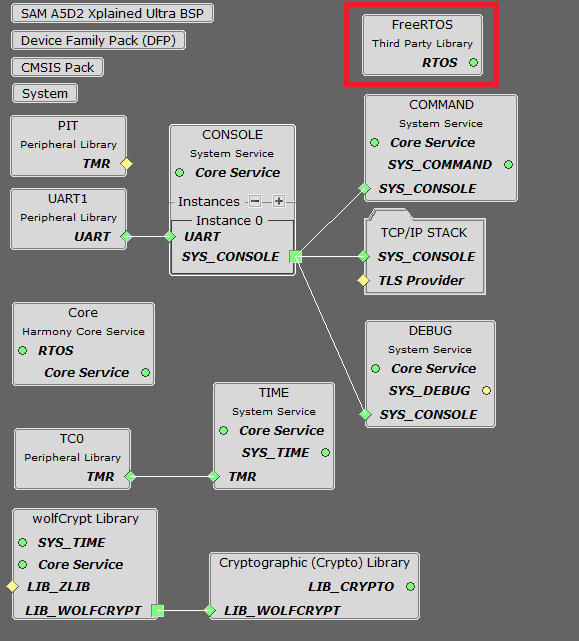
FreeRTOS component is required for RTOS application. For bare-metal (non-RTOS) FreeRTOS component should not be selected.
NOTE - The above diagram contains FreeRTOS component and that is required for RTOS application. For bare-metal(non-RTOS) FreeRTOS component shouldn't be selected.
TCP/IP Configuration - TCP/IP TCP Berkeley Client
The TCP/IP modules enabled for the demo is shown in the TCP/IP Configuration Overview
More details of TCP/IP Configuration plugin is available here
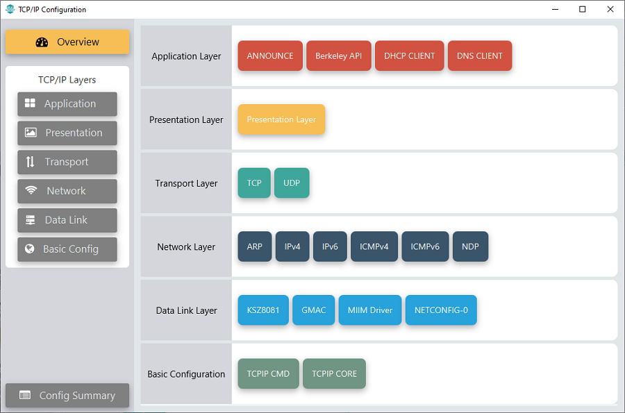
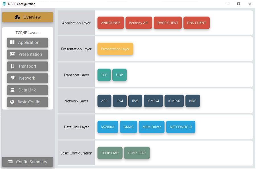
The Application Layer modules enabled in the demo are as follows:
- Application Layer Modules
- Announce to discover the Microchip devices within a local network.
- Berkeley API provides the Berkeley_Socket_Distribution (BSD) wrapper to the native Harmony TCP/IP Stack APIs
- DHCP Client to discover the IPv4 address from the nearest DHCP Server.
- DNS Client provides DNS resolution capabilities to the stack.
Downloading and Building the application
To clone or download this application from Github, go to the main page of this repository and then click Clone button to clone this repository or download as zip file.
This content can also be downloaded using content manager by following these instructions.
Path of the application within the repository is apps\berkeley_tcp_client\firmware .
To build the application, refer to the following list of demo configurations and open the project using MPLAB X IDE.
| Project Name | Target Device | Development Board | Description |
|---|---|---|---|
| sam_a5d2_xult.X | ATSAMA5D27 | SAMA5D2 Xplained Ultra | TCP/IP Berkeley TCP Client with an on-board KSZ8081 PHY - Bare Metal |
| sam_a5d2_xult_freertos.X | ATSAMA5D27 | SAMA5D2 Xplained Ultra | TCP/IP Berkeley TCP Client with an on-board KSZ8081 PHY - FreeRTOS |
| sam_a5d2_curiosity.X | ATSAMA5D29 | SAMA5D29-Curiosity | TCP/IP Berkeley TCP Client with an external KSZ8041 PHY - Bare Metal |
| sam_a5d2_curiosity_freertos.X | ATSAMA5D29 | SAMA5D29-Curiosity | TCP/IP Berkeley TCP Client with an external KSZ8041 PHY - FreeRTOS |
Hardware Setup - SAMA5D2 Xplained Ultra
The target board for running the application is SAMA5D2 Xplained Ultra.
This section provides essential hardware configuration of this target board to run TCP/IP applications.
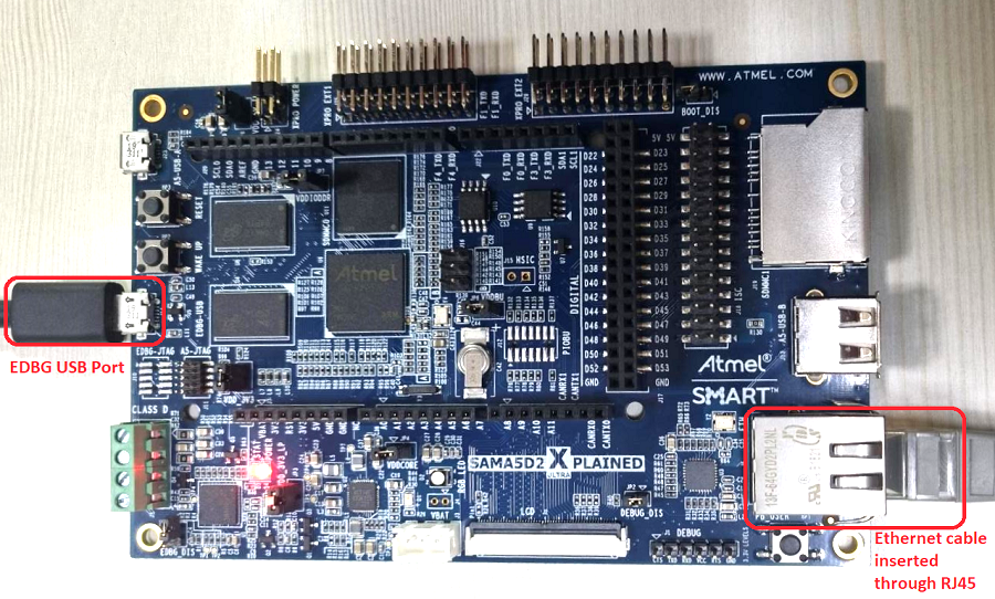
Board Setup
To set up the hardware, refer to the section Board Components in SAMA5D2 Xplained Ultra User Guide.
- Connect the micro USB cable from the computer to the EDBG USB connector on the SAMA5D2 Xplained Ultra Evaluation Kit.
- Establish a connection between the router/switch with the SAMA5D2 Xplained Ultra Evaluation Kit through the RJ45 connector.
Hardware Setup - SAMA5D29-Curiosity
The target board for running the application is SAMA5D29-Curiosity.
This section provides essential hardware configuration of this target board to run TCP/IP applications.
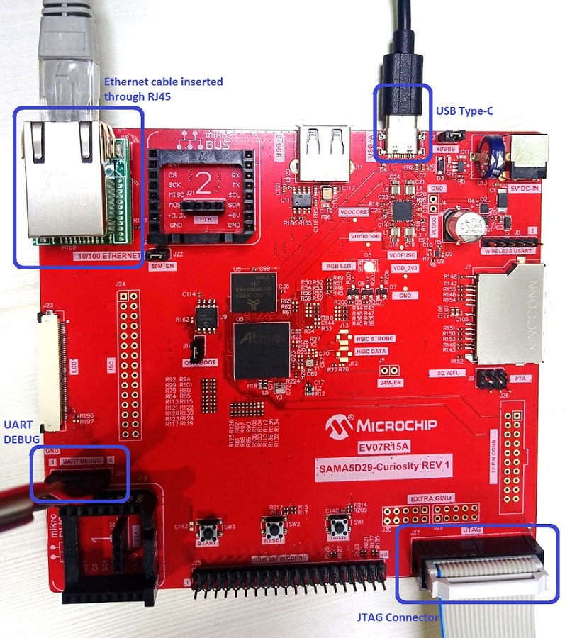
Board Setup
To set up the hardware, refer to the section Board Setup in SAMA5D29-Curiosity User Guide.
- Connect the USB Type-C cable from the computer to connector J1 (USB_A port) on the SAMA5D29-Curiosity Development Board.
- Connect a USB-UART converter from the computer to J28 (UART_DEBUG port) on the SAMA5D29-Curiosity Development Board.
- Connect the J32-Debug probe debugger/programmer from the computer to the J27 (JTAG connector) on the SAMA5D29-Curiosity Development Board.
- Establish a connection between the router/switch with the SAMA5D29-Curiosity Development Board through the RJ45 connector.
Setting up at91bootstrap loader
To load the application binary onto the target device, we need to use at91bootstrap loader.
Refer to the at91bootstrap loader documentation for details on how to configure and run/debug the application using MPLABX and booting application using an SD Card.
Running the Application
- Open a terminal application on the host computer (like Hyper-terminal or Tera Term).
- Configure the terminal application for serial port connected to USB-UART Port.
- Set baud rate as 115200 in the terminal application.
- Build and download the application project on the target board.
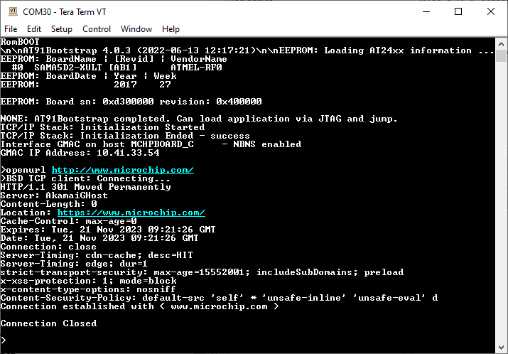
- Verify the TCP/IP Stack initialization console messages.
Console Start up
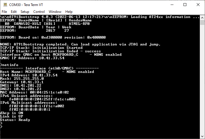
If DHCP client is enabled in the demonstration, wait for the DHCP server to assign an IP address for the development board.
This will be printed on the console. Otherwise, the default static IP address will be assigned to the board.
By entering the command netinfo, the response is obtained as shown above.
Berkeley TCP Client Test
Enter following command in console: openurl <url>. For example, openurl http://www.microchip.com/.
The response from the server will be printed on the console as shown below.
