
1.17 WLAN STA
This example application shows how to use the PIC32MZW1 WLAN APIs to configure the device in STA mode directly using the WLAN driver APIs.
Description
This application shows the various commands to be used for STA mode of PIC32MZW1 device. The user can use these commands in configuring the device that it wants to connect, scan operations, etc...
Downloading and building the application
To download or clone this application from Github, go to the top level of the repository and click

Path of the application within the repository is apps/wifi_sta/firmware .
To build the application, refer to the following table and open the project using its IDE.
| Project Name | Description |
|---|---|
| pic32mz_w1_curiosity_driver.X | MPLABX project for PIC32MZ W1 Curiosity Board |
Configuring the Application
Setting up a regulatory region
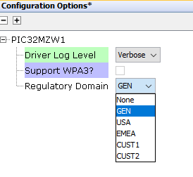
The available regulatory domains are - GEN, USA, EMEA, CUST1 and CUST2. One of these regulatory domains must be selected as an active domain. This selection can be done in two ways.
Using MHC
Figure below shows how to set the regulatory domain in MHC and the path is: TCPIP & SYS_CONSOLE -> TCP/IP STACK -> BASIC CONFIGURATION -> PIC32MZW1
Using command
wlan set regdomain <reg_domain_name> is the command used to set the regulatory domain. (wlan set regdomain USA – sets the regulatory domain to USA).
Note: User can change the regulatory domain using this command only if the current setting is "None" (cofigured using MHC)
Setting up the hardware
The following table shows the target hardware for the application projects.
| Project Name | Board |
|---|---|
| pic32mz_w1_curiosity_driver.X | PIC32MZ W1 Curiosity Board |
Setting up PIC32MZ W1 Curiosity Board
Connect the Debug USB port on the board to the computer using a micro USB cable
On the GPIO Header (J207), connect U1RX (PIN 13) and U1TX (PIN 23) to TX and RX pin of any USB to UART converter like USB UART click respectively
Running the Application
Open the Terminal application (Ex.:Tera term) on the computer
Connect to the "USB to UART" COM port and configure the serial settings as follows:
Baud : 115200
Data : 8 Bits
Parity : None
Stop : 1 Bit
Flow Control : None
Build and Program the application project using its IDE
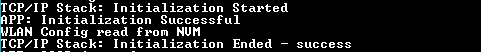
Console displays the initialization messages and WLAN config if already saved in NVM
Supported Commands
| Command | Description |
|---|---|
| wlan config <ssid> <ssid_length> <channel> <open/wpa2/wpam/wpa3/wep> <password> | Configures the SSID, SSID length, channel number and the security of the AP that DUT wants to connect. NOTE: Valid channel numbers are in range 1-13 and 0 or 255 - scans all channels |
| wlan connect | Connects the device to the AP configured in the command “wlan config” |
| wlan scan_options <num_slots> <active_slot_time in ms> <probes_per_slot> <passive_scan_time in ms> <stop_on_first> | Configure scan parameters |
| wlan scan <active / passive> <channel> | Runs either a active or passive scan (as per the input) on the channel number specified for the time set in "wlan scan_options". Note: If no time is set, default value is used |
| wlan scan_ssidlist <channel> <num_ssids> <ssid_list> | Scan a list of known SSID's (Maximum SSID is 4) |
| wlan set channel_mask <channel_mask> | Sets the channel mask for channel 1-13. Note: 1 for enable and 0 for disable |
| wlan get rssi | Gets the RSSI of current association |
| wlan save config | Stores the WLAN configurations given in command “wlan config” to flash memory. On restart an attempt is made to establish a connection to the AP based on the credentials stored in flash memory. |
| wlan set regdomain <reg_domain_name> | Sets the regulatory domain. |
| wlan get regdomain <all / current> | Displays the regulatory domain all – request all regulatory domains; current - request current regulatory domain |