1.2.2 Configuring The G3 ADP Layer
G3 Stack Configurator
G3 ADP (Adaptation) Layer configuration is located in the module named G3 Stack, which serves as configurator for every G3 Stack component.
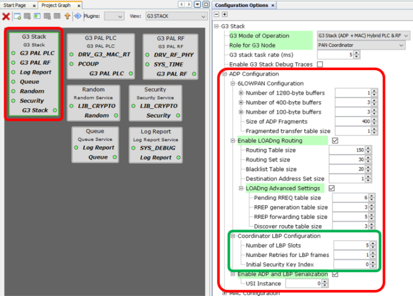
The figure shows the expanded configuration options for Adaptation layer.
A PAN Coordinator example is chosen, so the Coordinator LBP Configuration appears. For a PAN Device, this configuration is not shown in the Options pane.
6LoWPAN Configuration
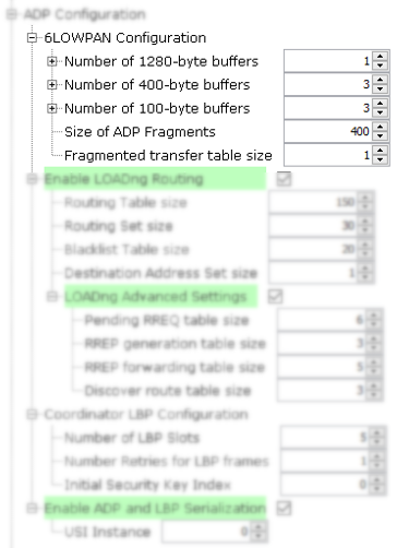
6LoWPAN configurable parameters are:
Transmission buffers. These are statically allocated and hold frames for transmission and their associated parameters. They are shared between application layer and internal protocols such as LBP and LOADng. There are 3 different buffers depending on their size:
Number of 1280-byte buffers.
Number of 400-byte buffers.
Number of 100-byte buffers.
Size of ADP Fragments. This parameter has to be defined according to the maximum size of MSDU, as it is the size of the fragments in which ADP will cut large frames before passing them to the MAC layer on transmission. The G3 Standard defines this parameter to be 400 bytes, but it is made configurable in case an implementation has further restrictions (for example using a PHY transceiver with limited capabilities).
Fragmented transfer table size. This parameter is for frame reception, and indicates how many frames (potentially split in fragments) can be received in parallel. In a typical G3 application, Devices only need room for 1 frame, and this is the default value, for Coordinators this value can be increased if needed (depending on the traffic generated by the application).
LOADng Configuration
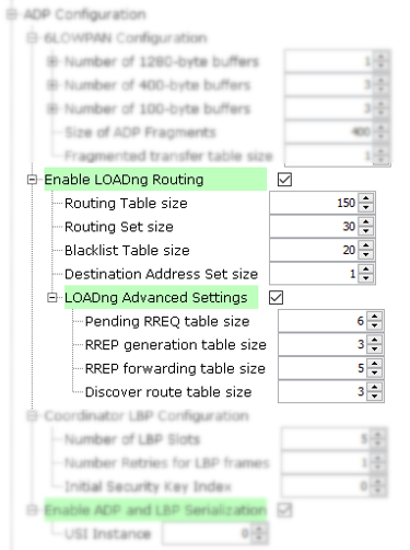
As explained in previous sections, LOADng is the Routing Protocol used by default by G3, but it can be disabled in case other Routing mechanism is used, or if no Routing is needed at all. So the first configuration options is whether to Enable LOADng or not, by means of Enable LOADng Routing checkbox.
When Enable LOADng Routing option is checked, the related configuration options appear:
Table Sizes. Default values for tables are dimensioned for a Device in a big G3 Network. They may be increased for a Coordinator of a big Network, or may be decreased for a Device in a small/medium Network. Small tables may lead to inefficiency in the G3 Network, but will not lead to any wrong behaviour or malfunction.
Routing Table size. Number of Routes to other nodes that can be stored in the node.
Routing Set size. Routing set is where potential next hops for a route are stored during the Route Request (RREQ) propagation, when the final route is validated via a Route Reply (RREP), the chosen entry is promoted to the Routing Table, and the rest are discarded.
Blacklist Table size. Number of nodes that can be Blacklisted. A node is blacklisted when a Route through it fails, and thus it is not allowed to be used as next hop when the route is created again.
Destination Address Set size. Destination Adrress Set is a mechanism to impersonate other Devices that are not part of the G3 Network. A node will respond to LOADng processes as it it was any of the Addresses present in its Destination Address Set. It is a very specific use case, and the default size is '1' to not misuse resources, but it is made available to the user in case the application requires this functionality.
Advanced Settings. This options have the recommended values by default, and shall be changed only when the user understands the implications of such change.
Pending RREQ table size. Indicates how many Route Request processes from other nodes can be handled in parallel. If this table is full, subsequent Route Request frames from other nodes will be silently dropped, and the Route will follow a different path if available, or will be retried later.
RREP generation table size. Number of Route Replies (RREPs) that can be generated by the node in response to different Route Requests where route destination is the node itself.
RREP forwarding table size. Similar to Pending RREQ table size but for Route Replies (RREPs), it is the number of RREP frames that can be forwarded in parallel.
Discover route table size. Number of Route Request processes that can be initiated and queued from the node.
LBP Configuration
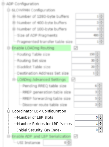
This configuration is only available when the Role is PAN Coordinator. Since Coordinator is the Server side on the Bootstrapping protocol, it has some options to control its behaviour. These options are:
Number of LBP Slots. The number of parallel bootstrapping Devices that it is able to attend. If more Devices try to Join the Network, they will be ignore until a free Slot is available.
Number of Retries for LBP frames. These retries are used in case a timeout occurs during the Bootstrapping phase of a Device (i.e. Device does not send the next LBP frame).
Initial Security Key Index. G3 Nodes are able to store 2 different Group Master Keys (GMKs) for operation. This parameter determines the index that will be used on Devices after bootstrapping, as it is a parameter set on Device during the bootstrap phase.
Serialization
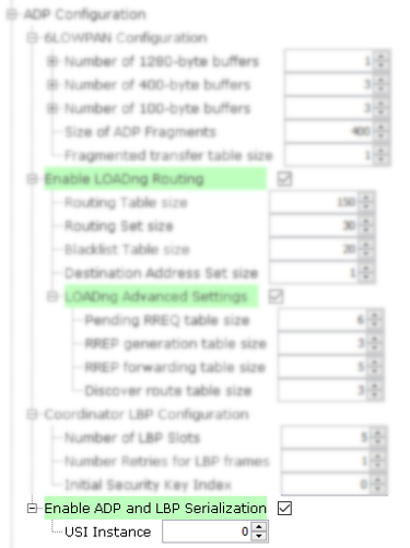
Adaptation layer API can be accessed from an external Host using a Serial Interface. To do so, USI module is used, and thus is has to be properly configured (refer to Smart Energy documentation). When Serialization is enabled, the USI instance to use has to be set, as shown in the figure above.
