
1 MPLAB® Harmony Smart Energy G3 Stack
The Smart Energy G3 Stack is the Microchip implementation of ITU G.9903 (G3-PLC®) standard. It is a Hybrid communication protocol which provides access to both PLC (PowerLine Communication) and RF media.
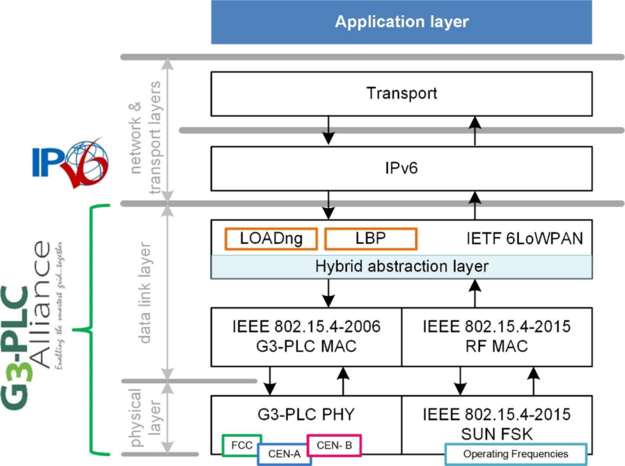
The following image shows the complete G3 protocol stack:
Note:
G3-PLC is the name that historically has been used to refer to the G3 communications stack since its inception, when only PLC medium was supported. G3-PLC, G3-Hybrid and G3 terms are used indistinctly in this documentation to refer to the same communications stack with PLC and RF capabilities.
G3 in a Nutshell
G3-PLC is an internationally standardized communication protocol stack gathering the advantages of an IPv6 compatible solution and offering high performances at the data link and physical layers. The OFDM physical layer embeds powerful error correction mechanisms based on a Reed-Solomon encoder followed by a convolutional encoder and a two-dimensional interleaver introducing time and frequency diversity, as well as an additional redundancy scheme with repetition codes.
Each OFDM subcarrier uses one of the following differential modulations: D8PSK, DQPSK and DBPSK. Optional coherent modulations offering a higher level of robustness (BPSK, QPSK, 8PSK) may be used. These modulations provide physical theoretical data rates of up to 44 kbps in the CENELEC-A bandplan and up to 280 kbps in the FCC bandplan.
In addition, channel estimation allows G3-PLC neighbour nodes to continuously adapt the robustness/data rate compromise by choosing the appropriate modulation but also to transmit data on the right OFDM subcarriers (tone mapping).
From a data link layer perspective, the MAC layer is based on an adapted version of the original IEEE 802.15.4-2006 standard including an enhanced CSMA/CA access method, acknowledgement of unicast frames, automatic repeat request (ARQ) and different priority levels to carry out QoS. The IETF 6LoWPAN-based adaptation layer allows IPv6 header compression (to limit the impact of the overhead imposed by the IPv6 protocol) and fragmentation for optimal IPv6 support but also provides a G3-PLC node with a routing algorithm optimized for the PLC medium: LOADng.
Security is also present at several layers of the G3-PLC communication stack. CCM* AES-128 ciphering is provided by the IEEE 802.15.4-based MAC layer and EAP-PSK authentication is provided by the adaptation layer allowing the secure association of G3-PLC nodes to a G3-PLC network.
The G3-Hybrid profile extends the existing G3-PLC protocol stack by providing a secondary radio frequency (RF) medium. The RF physical layer is based on SUN (Smart Utility Network) FSK, as specified in IEEE 802.15.4-2020 and amendment IEEE 802.15.4aa-2022. The RF MAC layer is based on IEEE 802.15.4-2015 which differs from the previous version of the standard used by the PLC MAC layer: IEEE 802.15.4-2006. Keeping the 2006 version for the PLC medium ensures that backwards compatibility is guaranteed with original G3-PLC networks.
The data link layer comprises a Hybrid Abstraction layer which has the main function to redirect the data flow to/from the appropriate interface (PLC and RF MAC service primitives, adaptation layer service primitives) while keeping the 6LoWPAN Adaptation layer mechanisms unchanged (same frame format, same IPv6 compression rules, use of the LowPAN Bootstrap Protocol, use of the mesh-under LOADng routing protocol). The only exception lies in the definition of a new link cost formula that takes into account the characteristics of RF links (link quality, duty cycles) intended for route cost computation during LOADng route discoveries.
G3 Stack Implementation in Harmony
The Harmony Smart Energy G3 Stack comprises the Data Link Layer shown in the above figure. Physical layers and Network & Transport layers are also part of the Harmony 3 ecosystem, but are considered pieces besides the G3 Stack, not part of it.
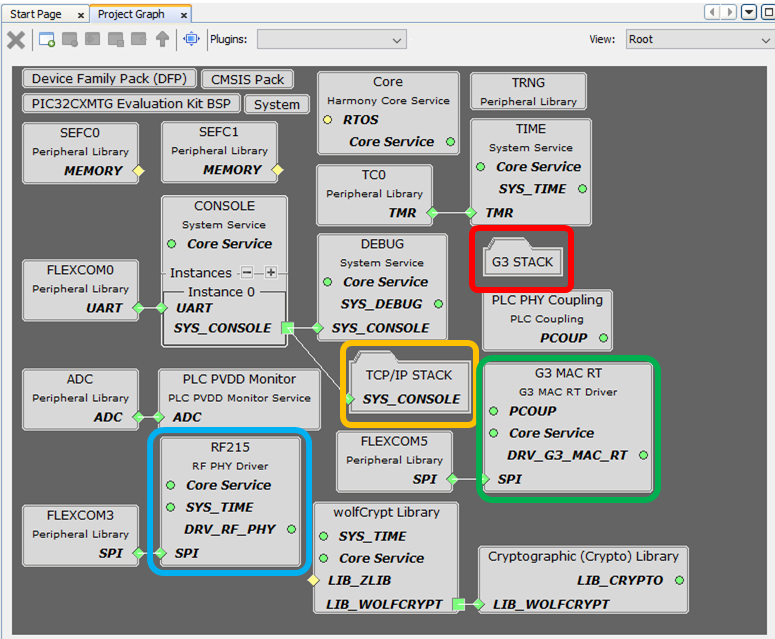
The following figure shows the MCC Project Graph of a G3 Device application, where the different modules are Highlighted:
The G3 Stack is highlighted in red. It corresponds to the data link layer in the Block Diagram on top of this page.
The TCP/IP Stack is highlighted in yellow. It corresponds to the network and transmport layers in the Block Diagram on top of this page.
The G3 MAC RT Driver is highlighted in blue. It partially corresponds to the G3-PLC PHY block in the Block Diagram on top of this page, but extending its capabilities to the lower layer of the G3-PLC MAC.
The RF PHY Driver is highlighted in green. It corresponds to the SUN FSK block in the Block Diagram on top of this page.
Double Clicking on the G3 Stack block, the G3 Stack View is opened, and there, the different implementation modules are presented:
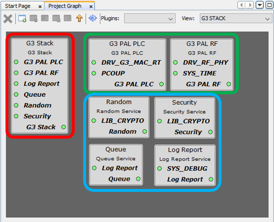
The G3 Stack block highlighted in red corresponds to the pure MAC and Adaptation Leyers of the data link layer.
The PAL blocks (PLC & RF) highlighted in green are modules in charge of adapting the IEEE 802.15.4 MAC layers to the Drivers below. This provides an abstraction from the MAC layers to the Physical layers, so changing the PAL contents, different PHYs (transceivers) can be used.
The G3 Auxiliary Services are highlighted in blue, they provide the following:
Random. Abstracts the generation of random numbers, MAC and ADP layers have a single API to generate random values, whathever the below implementation.
Security. Same as Random, abstracts a unique API from the security implementation below.
Queue. Implements a queing mechanism used by the G3 Adaptation layer that can be shared with other modules.
Log Report: G3 Stack code uses a tracing mechanism that outputs logging messages to a Console, this Service implements the connection to the Console, or turns functions into empty code in case tracing is not enabled.