1.15 TCP/IP TCP Server IPv4 Forwarding
The TCP/IP TCP Server IPv4 Forwarding configuration demonstrates creating a network server with two netwrok interfaces where IPv4 forwarding is enabled between the two interfaces. This demo uses the MPLAB Harmony TCP API to create
a TCP/IP echo server on port 9760.
an HTTP web server on a Microchip board. The Non-Volatile Memory (NVM) Microchip Proprietary File System (MPFS) is used for storing the web pages in the internal Flash.
The board is configured with dual ethernet interfaces with IPv4 forwarding, which are Internal ethmac & External Ethernet controller ENC624J600.
TCP/IP TCP Server IPv4 Forwarding MCC Configuration
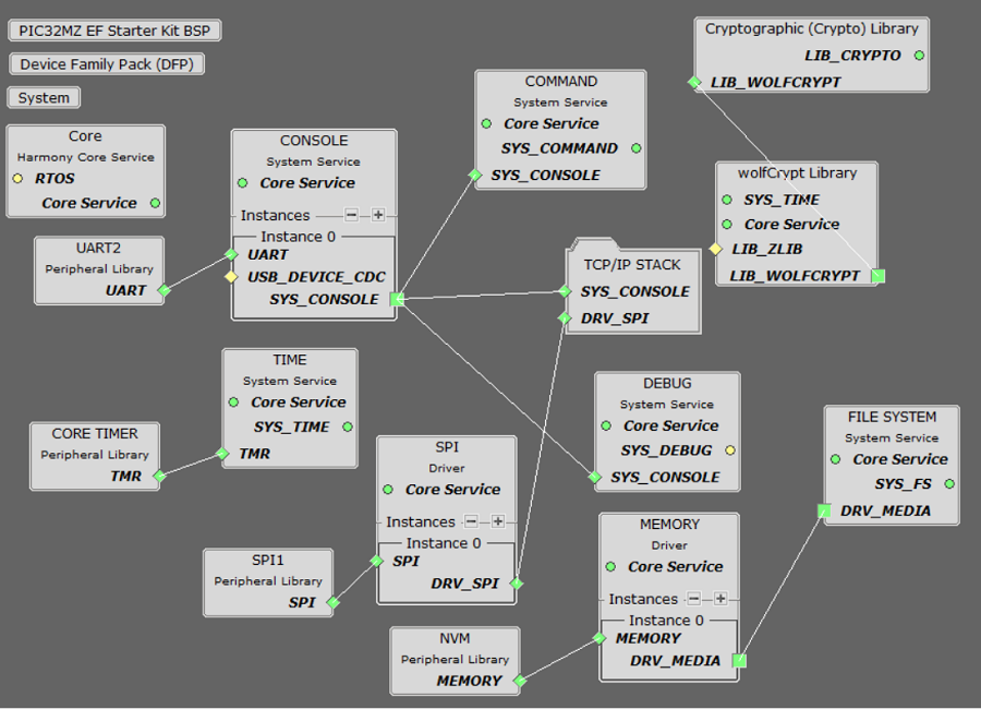
The following Project Graph diagram shows the Harmony components included in the TCP Server IPv4 Forwarding application demonstration.
MCC is launched by selecting Tools > Embedded > MPLAB® Code Configurator from the MPLAB X IDE and after opening the project, TCP/IP demo project is ready to be configured and regenerated.
TCP/IP Root Layer Project Graph
The root layer project shows that UART2 peripheral is selected to do read and write operation for TCP/IP commands.
This is the basic configuration with SYS_CONSOLE, SYS_DEBUG and SYS_COMMAND modules. These modules are required for TCP/IP command execution.
The ENCX24J600 daughter board use SPI driver and SPI1 peripheral library to communicate with the PIC32MZ EF Starter Kit -
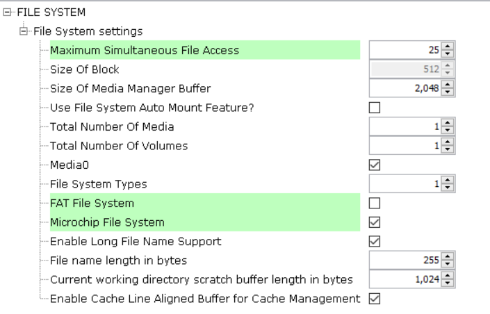
The file system component is required to select MPFS module. This is the below snapshot for the FS configuration.
TCP/IP Configuration
PIC32MZ EF Starter Kit
TCP/IP Required Application
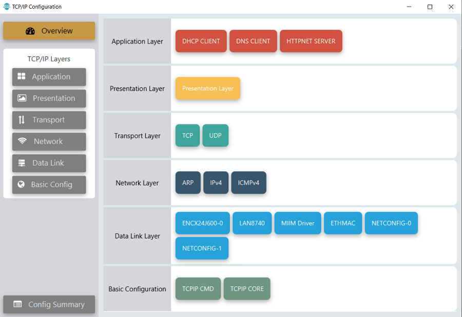
TCP/IP demo use these application module components for this demo.
DHCP Client module to discover the IPv4 address from the nearest DHCP Server.
DNS Client provides DNS resolution capabilities to the stack.
HTTPNET Server module is selected to run the web_server for the port number 80.
TCP/IP Data Link Layer
Internal ethernet driver(ethmac)
Internal ethernet driver(ethmac) is enabled with the external LAN8740 PHY driver library for the starter kit. The MIIM Driver supports asynchronous read/write and scan operations for accessing the external PHY registers and notification when MIIM operations have completed.
External ENCX24J600 ethernet driver
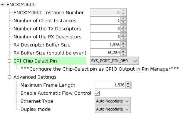
TCP/IP ENCX24J600 driver module selected for the external ethernet mac ENCX24J600 device. For high MAC TX and RX performance DRV_ENCX24J600_MAC_TX_DESCRIPTORS and DRV_ENCX24J600_MAC_RX_DESCRIPTORS can be configured respectively more than the default descriptor value size "3".
Refer below for the components selected in the Data Link Layer of the TCP/IP stack

GPIO RE9 pin is configured for SPI chip select.
TCP/IP Network Layer
IPv4
Enable IPv4 Forwarding support & configurations:
Refer to the below shown configurations made for the demonstration, which invloves specifying the IPV4 Forwarding table entries.
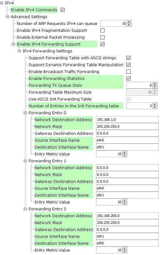
TCP/IP TCP Server IPv4 Forwarding Hardware Configuration
This section describes the hardware configuration for PIC32MZ EF Starter Kit and one can be used for the respective application demonstration.
This section describes PIC32MZ EF Starter Kit custom hardware configuration which uses the on-board debugger and programmer with Internal ethmac and External Ethernet controller ENC624J600 for this application demonstration.
Refer to the PIC32MZ EF Starter Kit User Guide for the programming/debugging options supported & setting up the hardware.
Refer to the Starter Kit I/O Expansion Board - DM320002 User Guide
Refer to the ENC624J600 External Ethernet PICtail Plus Daughter Board
The Fast 100Mbps Ethernet PICtail Plus Daughter Board is inserted to J2(or J4) on the Starter Kit I/O Expansion Board. The J2, PICtail Plus (SPI) connector on Fast 100Mbps Ethernet PICtail Plus Daughter Board is attached to I/O Expansion Board with white arrows on the two boards lined up. The PICtail daughter board is inserted to use SPI1.
Connect the 168 pin to 132 pin Starter Kit Adapter board to the Starter Kit I/O Expansion Board (DM320002), optionally use a nylon nut and bolt to secure the two boards together
Connect the PIC32MZ EF Starter kit to the 168 pin to 132 pin Starter Kit Adapter board, optionally use a nylon nut and bolt to secure the two boards together
Connect the mini USB cable from the computer to the USB DEBUG connector on the PIC32MZ EF Starter Kit
Connect the mini USB cable from the computer to the USB-UART connector on the PIC32MZ EF Starter Kit
Please refer to the following figure for GPIO PIN RE9.
The pin 46 on J10 and pin 47 on J11 (on I/O Expansion board) need to be connected to control the Chip-Select ( GPIO RE9 configuration ) line by the board.
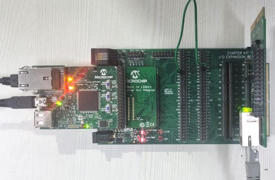
Note: In this demo, GPIO RE9 pin is configured for SPI chip select.
We have two host, (refer to the below network setup diagram)
Establish a connection between the Host 2 with the PIC32MZ EF Starter Kit through the RJ45 connector on LAN8740 PHY daughter board
Establish a connection between the PC 1 with the PIC32MZ EF Starter Kit through the RJ45 connector on External ENC624J600 daughter board
TCP/IP TCP Server IPv4 Forwarding Running Application
This table list the name and location of the MPLAB X IDE project folder for the demonstration.
| Project Name | Target Device | Target Development Board | Description |
|---|---|---|---|
| pic32mz_ef_sk_encx24j600.X | PIC32MZ2048EFH144 | PIC32MZ EF Starter Kit(with LAN8740 PHY) + External Ethernet Pictail Controller ENCX24J600 + I/O Expansion Board(with 168 pin to 132 pin Starter Kit Adapter board) | Demonstrates the TCP Server IPv4 Forwarding on development board with PIC32MZ2048EFH144 device with LAN8740 PHY and external Ethernet controller ENCX24J600 daughter board. This is a bare-metal (non-RTOS) implementation |
Running Demonstration Steps
Build and download the demonstration project on the target board.
If the board has a UART connection:
A virtual COM port will be detected on each of the host, when the USB cable is connected to USB-UART connector.
Open a standard terminal application on each of the host (like Hyper-terminal or Tera Term) and configure the virtual COM port.
Set the serial baud rate to 115200 baud in the terminal application.
See that the initialization prints on the serial port terminal.
Assigning the static IP address & create two different networks:
The IP address of all the network nodes at the interface0 (eth0) side in the test setup must be configured to have the first three octects same (for an IPV4 address).
The IP address of all the network nodes at the interface1 (eth1) side in the test setup must be configured to have the first three octects same (for an IPV4 address).
Please see the below shown network setup and connections between the nodes:
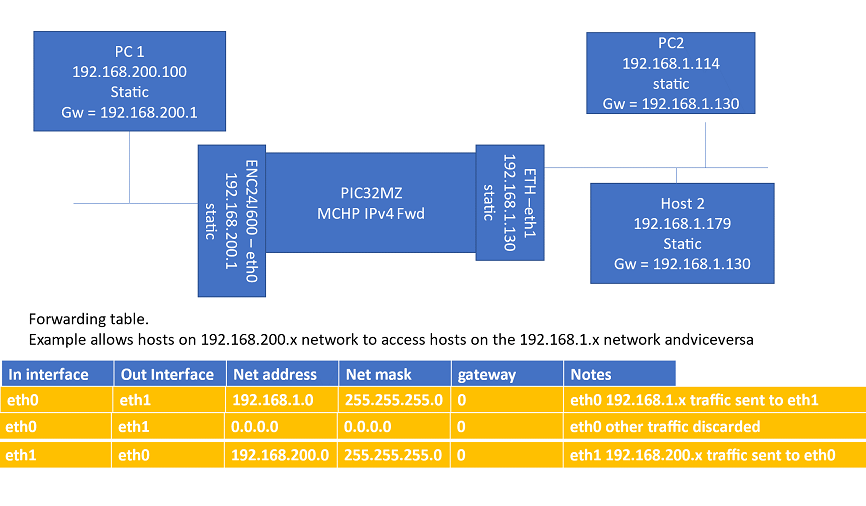
It is recommended to disconnect any other network connections (like WiFi, etc) on the nodes involved in the test.
Execution :
As soon as the IP address is assigned to the board , it is ready to accept a TCP/IP connection on port 9760.
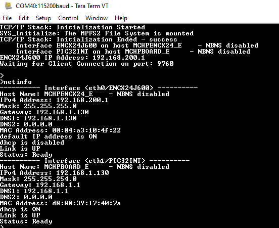
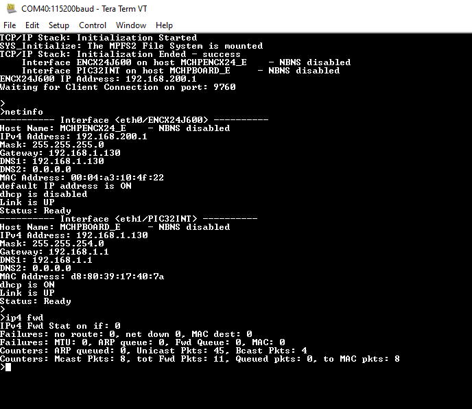
IPv4 forwarding test setup console screenshots:
By entering the command ip4 fwd, the response is obtained as shown below.
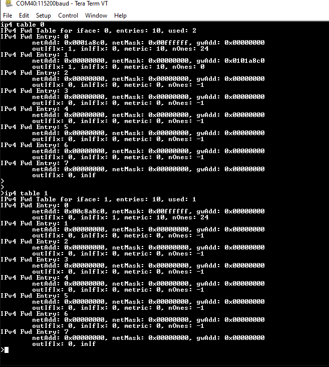
By entering the command ip4 table 0 and ip4 table 1, the response is obtained as shown below.
Ping Test -
As per the network setup, PC1 can ping PC2 and vice versa
Demo Test -
PC1 can access web pages using 192.168.1.130 address (eth1) andPC2 can access web pages using 192.168.200.1 address (eth0) .
