1.6 TCP/IP IPERF Application
Iperf is a tool for the measurement of maximum achievable throughput of a network device on IP networks.
The Iperf demo creates an application to run Iperf on target board and measure the network performance.
TCP/IP IPERF Application MCC Configuration
The following Project Graph diagram shows the Harmony components included in the IPERF Application application demonstration.
MCC is launched by selecting Tools > Embedded > MPLAB® Code Configurator from the MPLAB X IDE and after opening the project, TCP/IP demo project is ready to be configured and regenerated.
TCP/IP Root Layer Project Graph
The root layer project shows that UART2 peripheral is selected to do read and write operation for TCP/IP commands.
This is the basic configuration with SYS_CONSOLE, SYS_DEBUG and SYS_COMMAND modules. These modules are required for TCP/IP command execution.
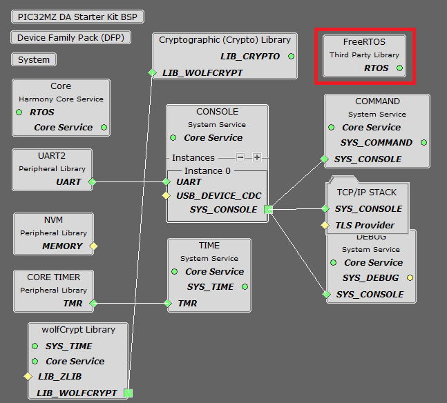
NOTE - The above diagram contains FreeRTOS component and that is required for RTOS application. For bare-metal(non-RTOS) FreeRTOS component shouldn't be selected.
TCP/IP Configuration
PIC32MZ DA Starter Kit / PIC32MZ EF Starter Kit
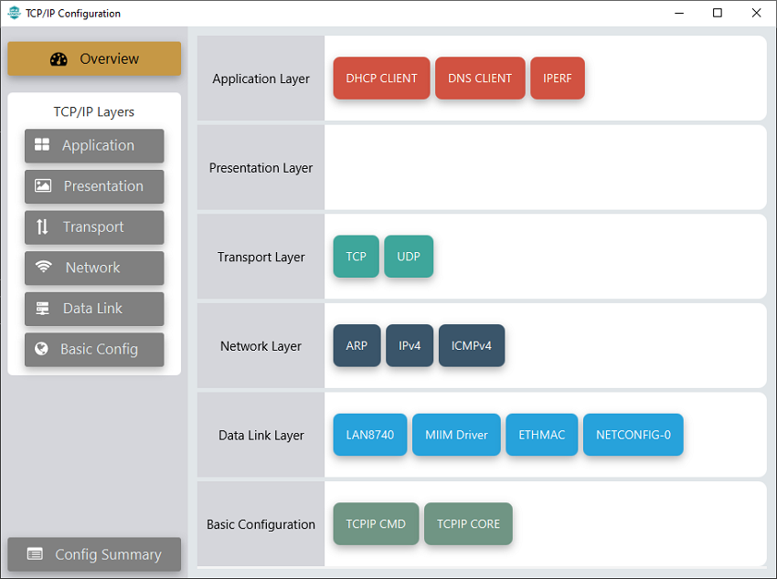
TCP/IP Required Application
TCP/IP demo use these application module components for this demo.
DHCP Client module to discover the IPv4 address from the nearest DHCP Server.
DNS Client provides DNS resolution capabilities to the stack.
IPERF implements the iPerf protocol to measure networking bandwidth and performance.
IPERF module is used to run the network benchmark program.
The default sizes of the Iperf RX and TX buffers are set to 4KB. The performance of a socket is highly dependent on the size of its buffers. So it's a good idea to use as large as possible buffers for the sockets that need high throughput. Bigger buffers will help obtain higher performance numbers.
The other iperf parameters could be left with their default values.
For a description of the parameters see the Iperf Module of the TCP/IP Library.
TCP/IP Data Link Layer
Internal ethernet driver(ethmac) is enabled with the external LAN8740 PHY driver library for both the starter kits. The MIIM Driver supports asynchronous read/write and scan operations for accessing the external PHY registers and notification when MIIM operations have completed.
TCP/IP IPERF Application Hardware Configuration
This section describes the hardware configuration for PIC32MZ DA/EF Starter Kit and one can be used for the respective application demonstration.
This section describes the PIC32MZ DA Starter Kit default hardware configuration which uses the on-board debugger and programmer for this application demonstration.
Refer to the PIC32MZ DA Starter Kit User Guide for the programming/debugging options supported & setting up the hardware.
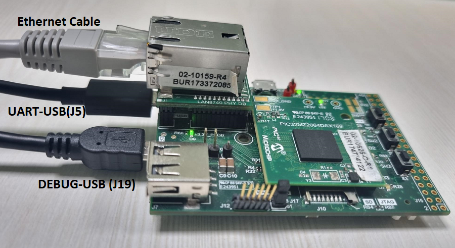
Connect micro USB cable from the computer to the DEBUG USB connector(J19) on the PIC32MZ DA Starter Kit
Connect micro USB cable from the computer to the USB-UART connector(J5) on the PIC32MZ DA Starter Kit
Establish a connection between the router/switch with the PIC32MZ DA Starter Kit through the RJ45 connector on PHY daughter board
This section describes the PIC32MZ EF Starter Kit default hardware configuration which uses the on-board debugger and programmer for this application demonstration.
Refer to the PIC32MZ EF Starter Kit User Guide for the programming/debugging options supported & setting up the hardware.
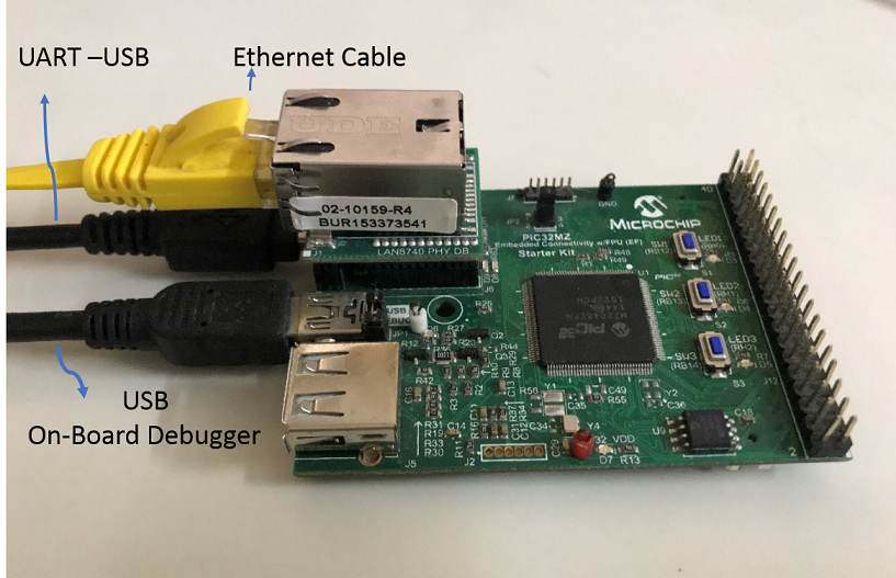
Connect the mini USB cable from the computer to the USB DEBUG connector on the PIC32MZ EF Starter Kit
Connect the mini USB cable from the computer to the USB-UART connector on the PIC32MZ EF Starter Kit
Establish a connection between the router/switch with the PIC32MZ EF Starter Kit through the RJ45 connector on PHY daughter board
TCP/IP IPERF Application Running Application
This table list the name and location of the MPLAB X IDE project folder for the demonstration.
| Project Name | Target Device | Target Development Board | Description |
|---|---|---|---|
| pic32mz_das_sk.X | PIC32MZ2064DAS169 | PIC32MZ DA Starter Kit | Demonstrates the IPERF Application on development board with PIC32MZ2064DAS169 device and LAN8740 PHY daughter board. This implementation is based on bare-metal(non-RTOS). |
| pic32mz_das_sk_freertos.X | PIC32MZ2064DAS169 | PIC32MZ DA Starter Kit | Demonstrates the IPERF Application on development board with PIC32MZ2064DAS169 device and LAN8740 PHY daughter board. This implementation is based on FreeRTOS. |
| pic32mz_ef_sk.X | PIC32MZ2048EFH144 | PIC32MZ EF Starter Kit | Demonstrates the IPERF Application on development board with PIC32MZ2048EFH144 device and LAN8740 PHY daughter board. This implementation is based on bare-metal(non-RTOS). |
| pic32mz_ef_sk_freertos.X | PIC32MZ2048EFH144 | PIC32MZ EF Starter Kit | Demonstrates the IPERF Application on development board with PIC32MZ2048EFH144 device and LAN8740 PHY daughter board. This implementation is based on FreeRTOS. |
Running Demonstration Steps
Build and download the demonstration project on the target board.
If the board has a UART connection:
A virtual COM port will be detected on the computer, when the USB cable is connected to USB-UART connector.
Open a standard terminal application on the computer (like Hyper-terminal or Tera Term) and configure the virtual COM port.
Set the serial baud rate to 115200 baud in the terminal application.
See that the initialization prints on the serial port terminal.
When the DHCP client is enabled in the demonstration, wait for the DHCP server to assign an IP address for the development board. This will be printed on the serial port terminal.
Alternatively: Use the Announce service or ping to get the IP address of the board.
Run tcpip_discoverer.jar to discover the IPv4 and IPv6 address for the board.
Execution :
After the successful board bring up, the console output becomes
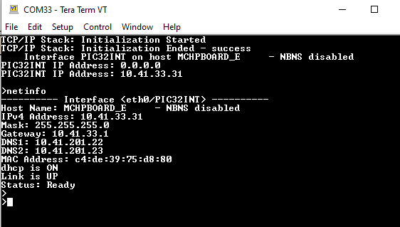
Test and Output:
The iperf demo is interactive, using a set of special iperf commands that are supported by the standard set of TCP/IP commands.
Pressing "help iperf" at the command prompt displays the list of the available iperf commands/options:
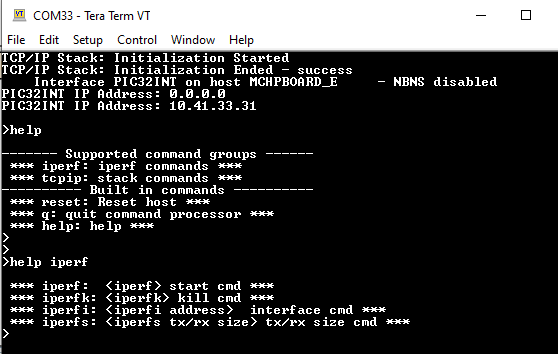
A brief description of the most important settings/commands follows:
"iperf": starts the iperf session. Use "iperf -s" for a server connection or "iperf -c address" for a client connection
Look at the Iperf Module for the command syntax.
"iperfk": kills an ongoing iperf test. This is mainly useful for killing a iperf server waiting for connections. But the command could be also used to abort client test.
"iperfi": to set the interface to use for iperf when the test is run on a multi-interface host. When multiple iperf instances are used, the extra parameter "-i" should be used to specify the iperf index to which the command refers to.
"iperfs": to set the socket TX or RX buffer size dynamically. For example:
"iperfs -tx 2048"
Note:
The iperf demo uses very few TCP/IP modules, to minimize the stack overhead and to obtain good throughput numbers.
However ICMP server, NBNS and Announce modules are enabled to assist in the discovery of the board on the network.
DHCP client is also enabled for acquiring a valid IP address within the network.
Some of these modules could be further disabled if they are not used in the specific network environment of the application.
The data throughput could vary dependent on the iperf socket settings and the network conditions.
Larger TX and RX buffers will increase the corresponding throughput.
Various devices on the network on the link between the board and the machine running the iperf application (switches, routers, etc.) could also affect the throughput.
User can eliminate these effects by connecting the board running the iperf demo directly to the machine running the test on the PC side (Linux, Windows, etc.)
