![]()
OCMP compare mode
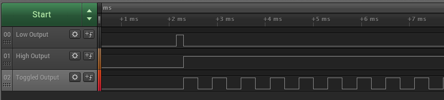
This example application shows how to use the OCMP peripheral to generate an active low, active high, and toggle output on compare match.
Description
In this application, three OCMP modules are used to generate waveforms.
Active Low Output: By default output is set as high and it is set as low on the compare match
Active High Output: By default output is set as low and it is set as high on the compare match
Toggled Output: Compare match toggles the output
Downloading and building the application
To clone or download this application from Github, go to the main page of this repository and then click Clone button to clone this repository or download as zip file. This content can also be downloaded using content manager by following these instructions.
Path of the application within the repository is apps/ocmp/ocmp_compare_mode/firmware .
To build the application, refer to the following table and open the project using its IDE.
| Project Name | Description |
|---|---|
| pic32mx470_curiosity.X | MPLABX project for Curiosity PIC32MX470 Development Board |
| pic32mx_eth_sk2.X | MPLABX project for PIC32 Ethernet Starter Kit |
| pic32mx_xlp_sk.X | MPLABX project for PIC32MX274 XLP Starter Kit |
| pic32mx_sk.X | MPLABX project for PIC32MX Starter Kit |
Setting up the hardware
The following table shows the target hardware for the application projects.
| Project Name | Board |
|---|---|
| pic32mx470_curiosity.X | Curiosity PIC32MX470 Development Board |
| pic32mx_eth_sk2.X | PIC32 Ethernet Starter Kit |
| pic32mx_xlp_sk.X | PIC32MX274 XLP Starter Kit |
| pic32mx_sk.X | PIC32MX Starter Kit |
Setting up Curiosity PIC32MX470 Development Board
- Connect mini USB cable to the ‘Debug USB’ connector(J3) on the board to the computer
Setting up PIC32 Ethernet Starter Kit
- Connect mini USB cable to the ‘Debug USB’ connector(J7) on the board to the computer
Setting up PIC32MX274 XLP Starter Kit
- Connect micro USB cable to the ‘Debug USB’ connector(J9) on the board to the computer
Setting up PIC32MX Starter Kit
- Connect mini USB cable to the ‘Debug USB’ connector(J1) on the board to the computer
Running the Application
- Build and program the application project using its IDE
-
Observe active low, active high and toggle output on the oscilloscope
-
Refer the following table for pin details:
OCMP output Curiosity PIC32MX470 Development Board pins PIC32 Ethernet Starter Kit and PIC32MX Starter Kit pins PIC32MX274 XLP Starter Kit pins OC1 output RPD0 “Pin 6 of J14” RD0 “LED1” RC7 “Pin 5 of J2” OC2 output RPG9 “Pin 10 of J14” RD1 “LED2” RA8 “Pin 13 of J2” OC3 output RPB9 “Pin 3 of J14” RD2 “LED3” RB14 “Pin 12 of J2”