![]()
ADC interrupt
This example demonstrates how to sample an analog input in interrupt mode and send the converted data to console.
Description
In this example, Analog input voltage in the range of 0 V to 3.3 V is fed to the ADC and converted value is displayed on the console. The ADC conversion is triggered by software and result is read in the conversion complete interrupt handler.
Downloading and building the application
To clone or download this application from Github, go to the main page of this repository and then click Clone button to clone this repository or download as zip file. This content can also be downloaded using content manager by following these instructions.
Path of the application within the repository is apps/adc/adc_interrupt_mode/firmware .
To build the application, refer to the following table and open the project using its IDE.
| Project Name | Description |
|---|---|
| pic32mx470_curiosity.X | MPLABX project for Curiosity PIC32MX470 Development Board |
| pic32mx_xlp_sk.X | MPLABX project for PIC32MX274 XLP Starter Kit |
Setting up the hardware
The following table shows the target hardware for the application projects.
| Project Name | Board |
|---|---|
| pic32mx470_curiosity.X | Curiosity PIC32MX470 Development Board |
| pic32mx_xlp_sk.X | PIC32MX274 XLP Starter Kit |
Setting up Curiosity PIC32MX470 Development Board
- Connect mini USB cable to the ‘Debug USB’ connector(J3) on the board to the computer
- Install an USB UART click board on to the mikroBUS socket J5
- Connect mini USB cable to the USB UART click board. This will enumerate the USB to UART port
- AN9 pin is used for analog input
- Use a jumper wire to connect Pin 3 of J14 (AN9 is mapped to Port Pin RPB9) to 3.3 V or GND or external supply Note: Ensure that the series resistors on the mikroBUS headers are of value 0 Ohms
Setting up PIC32MX274 XLP Starter Kit
- Connect micro USB cable to the ‘Debug USB’ connector(J9) on the board to the computer
- Install an USB UART click board on to the mikroBUS socket J5
- Connect mini USB cable to the USB UART click board (This will enumerate the USB to UART port)
- AN7 pin, which is coming on switches S1 to S5, is used for analog input
Running the Application
- Open the Terminal application (Ex.:Tera term) on the computer
- Connect to the “USB to UART” COM port and configure the serial settings as follows:
- Baud : 115200
- Data : 8 Bits
- Parity : None
- Stop : 1 Bit
- Flow Control : None
- Build and Program the application project using its IDE
-
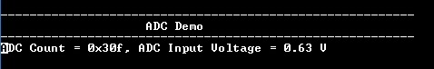
Console displays the ADC count and the ADC input voltage
- For PIC32MX274 XLP Starter Kit, switches S1 to S5 can be pressed in different combinations to get different output