![]()
DMAC CRC-32 Generation
This example application demonstrates how to use the DMAC peripheral to compute 32-bit Cyclic Redundancy Checksum (CRC).
Description
The DMAC unit provides support for calculating a CRC-16 and CRC-32 value for data passing through any DMA channel.
This example application computes the 32-bit CRC value for the poynomial (0x04C11DB7) using the CRC engine in DMAC peripheral.
It uses a DMA Channel with software trigger to initiate a memory-memory transfer from the source buffer to the destination buffer with 8-bit beat size. Once the transfer is completed a 32-bit CRC will be generated for the source buffer.
Once the hardware CRC is generated using a DMA Channel it is validated using a software-calculated CRC value.
Downloading and building the application
To clone or download this application from Github, go to the main page of this repository and then click Clone button to clone this repository or download as zip file. This content can also be downloaded using content manager by following these instructions.
Path of the application within the repository is apps/dmac/dmac_crc32_generate/firmware .
To build the application, refer to the following table and open the project using its IDE.
| Project Name | Description |
|---|---|
| pic32mx470_curiosity.X | MPLABX project for Curiosity PIC32MX470 Development Board |
Setting up the hardware
The following table shows the target hardware for the application projects.
| Project Name | Board |
|---|---|
| pic32mx470_curiosity.X | Curiosity PIC32MX470 Development Board |
Setting up Curiosity PIC32MX470 Development Board
- To run the demo, the following additional hardware are required:
- Connect mini USB cable to the ‘Debug USB’ connector(J3) on the board to the computer
- Install an USB UART click board on to the mikroBUS socket J5
- Connect mini USB cable between PC and the USB UART click board
- Note: Ensure that the series resistors on the mikroBUS headers are of value 0 Ohms
Running the Application
- Open the Terminal application (Ex.:Tera term) on the computer
- Connect to the “USB to UART” COM port and configure the serial settings as follows:
- Baud : 115200
- Data : 8 Bits
- Parity : None
- Stop : 1 Bit
- Flow Control : None
- Build and Program the application project using its IDE
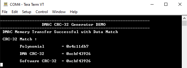
- Following message is output on console:
- Expected CRC Value for the polynomial (0x04C11DB7) is (0xcbf43926)
- The LED indicates the success or failure:
- LED is turned ON when the DMAC memory transfer is successful and hardware CRC value matches with the software calculated CRC value
Following table provides LED names:
| Board | LED Name |
|---|---|
| Curiosity PIC32MX470 Development Board | LED1 |