
4.7.7 Zigbee Custom Cluster Example
Introduction
Zigbee specification supports custom cluster, which is also called manufacturer defined cluster. Due to not all application are defined as standard Zigbee clusters, user can use this approach to define his own cluster including attributes and commands, to meet these special application requirements.
Microchip provided custom cluster feature in Zigbee library, the custom cluster can be easily edited using MCC GUI, generated code and run. Following sections describe a defined custom cluster, demo, and how to create the application from scratch.
Custom Cluster - Flowrate Monitor Definitions
As an example, define a custom cluster and use it into the demo code. Following are the cluster definitions:
Cluster name: flowRateMonitor
Cluster ID: 0xFC00
Server Attributes:
Attribute ID | Attribute Name | Data Type | Access & Report |
0x0000 | VolumetricRate | int16 | Read Only & Reportable |
0x0001 | Temperature | int16 | Read Only |
0x0002 | Pressure | int16 | Read Only |
0x0003 | Velocity | int16 | Read Only |
0x0004 | Density | uint16 | Read Only |
0x0005 | Vibration | int16 | Read Only |
0xFFFD | ClusterRevision | uint16 | Read Only |
Client Attributes:
Attribute ID | Attribute Name | Data Type | Access & Report |
0xFFFD | ClusterRevision | uint16 | Read Only |
Server Commands:
There is no custom command is defined for this cluster, but all standard command like Read Attribute Command, Read Attribute Response command, Report Attribute Command are supported by custom cluster as one default feature.
Client Commands:
There is no custom command is defined for this cluster, but all standard command like Read Attribute Command, Read Attribute Response command, Report Attribute Command are supported by custom cluster as one default feature.
Hardware Requirement
|
Tool |
Quantity |
|---|---|
WBZ451(or WBZ351) Curiosity Board | 2 |
Micro USB Cable | 2 |
Personal Computer | 1 |
Motion Click board | 1 |
SDK Setup
Software Requirement
TeraTermProgramming the Precompiled Hex File
This demo includes both cluster server and cluster client, which includes two example code project: custom_cluster_server project and custom_cluster_client proect. In each project folder, their precompiled hex file are provided. So, program one WBZ451/WBZ351 Curiosity board with custom_cluster_server.X.production_1.0.0.0.hex, which acts as cluster server and Zigbee end device role, and program second WBZ451/WBZ351 Curiosity board with custom_cluster_client.X.production_1.0.0.0.hex, which acts as cluster client and Zigbee coordinator role.
Board can be programmed by either IPE or MPLABX IDE.
- Custom_cluster_server
precompiled Hex file is located in "
<Harmony Content Path>\wireless_apps_pic32cxbz2_wbz45\apps\zigbee\custom_cluster_server\hex"OR "<Harmony Content Path>\wireless_apps_pic32cxbz3_wbz35\apps\zigbee\custom_cluster_server\hex"folder. - Custom_cluster_client
precomplied precompiled Hex file is located in "<Harmony Content
Path>
\wireless_apps_pic32cxbz2_wbz45\apps\zigbee\custom_cluster_client\hex"OR "<Harmony Content Path>\wireless_apps_pic32cxbz3_wbz35\apps\zigbee\custom_cluster_client\hex"folder. - Program two Curiosity boards with two precompiled hex files by following the steps mentioned here
- Follow steps mentioned in Running a Precompiled Example .
- Open and program the
Application Example “
custom_cluster_server.x" located in "<Harmony Content Path>\wireless_apps_pic32cxbz2_wbz45\apps\zigbee\custom_cluster_server\firmware"or "<Harmony Content Path>\wireless_apps_pic32cxbz3_wbz35\apps\zigbee\custom_cluster_server\firmware"using MPLABX IDE - Open and program the Application Example “combinedInterface.x" located in "<Harmony Content Path>\wireless_apps_pic32cxbz2_wbz45\apps\zigbee\combinedInterface\firmware" or "<Harmony Content Path>\wireless_apps_pic32cxbz3_wbz35\apps\zigbee\combinedInterface\firmware" using MPLABX IDE
-
For more details on how to find the Harmony Content Path, refer to Installing the MCC Plugin Installing the MCC Plugin
Demo Description
The demo application demonstrates the Zigbee custom cluster functionality of PIC32CXBZ/WBZ family of devices and modules. It consists of a cluster server application(ZigBee End device) and a cluster client application(Zigbee coordinator device) implemented as shown below:
|
Application |
Zigbee Logical Device Type |
Functionality |
|---|---|---|
custom_cluster_server | End Device | Device capable of join to Zigbee network formed by coordinator, it can also start distributed network if no network to join. After joining, it starts report attribute values to cluster client. |
Custom_cluster_client | Coordinator | Device capable of form a Zigbee network. After custom_cluster_server device join, it gets and display attribute report from cluster server periodically. It can also use command to read attribute values in cluster server. |
Zigbee device commissioning:
The Zigbee end device or router i.e. custom_cluster_server can be commissioned and brought to the existing zigbee network formed by Zigbee coordinator i.e. Combined Interface, the Zigbee router can also create new zigbee Distributed network (if there is no nearby network).
Custom cluster attribute report and read:
Custom_cluster_server demo can priodically report its attribute to customer_cluster_client demo, which can print the value received on Tera Term.
Custom_cluster_client demo can print the attribute value received from custom_cluster_server on Tera Term. Custom_cluster_client can also manually read each attribute values stored in custom_cluster_server by readAttribute command.
Demo Steps
Supply both WBZ451/WBZ351 Curiosity Board programmed with correct hex files by connecting a USB cable, power supply Green LED will turn on when connect to PC.
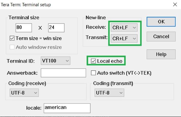
Open Tera Term software for both boards, setup serial port with correct COM port number and settings as 115200/8bit/none parity/1 stop bit/none flow control, enable Local echo and sending line ends with line feeds.
Tera Term setup
Input command resetToFN command on custom_cluster_client first, then input same resetToFN command on custom_cluster_server side, custom_cluster_server end device then will join to custom_cluster_client coordinator device, and below log will be shown about device successful commissioning:
Commissioning and custom cluster attribute report
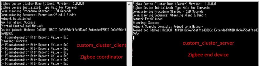
After commissioning, logs "Flowratemonitor Attr Report: Value = 0x0" are shown about periodical attribute report from custom_cluster_server.
On custom_cluster_client, input readAttribute -s 0xAAAA 0x30 0xfc00 0xB command, it can read specific attribute value from custom_cluster_server manually.
-s means 16btis short address to be used.
0xAAAA is the 16bits short address of end device(custom_cluster_server example) assigned by coordinator device(custom_cluster_client example), the short address can be known from the commissioning logs. If don't know the short address, can also input getNetworkAddress command on custom_cluster_server terminal to get it.
0x30 is the end point address of custom_cluster_server example. Since custom_cluster_server uses custom device type, its end point address is 0x30, this can be checked in its MCC graph.
0xfc00 is Cluster ID of custom cluster, it can be modified in MCC graph.
0xB is Attribute ID defined in cluster. For example, in this example, Attribute ID is range from 0x0 to 0x5 and 0xFFFD.
Creating Application From Scratch Using MCC
- Follow steps in Generating project from MCC to create a new Zigbee project, add Zigbee component by device type, and USART, SERCOM0, configure receiving pin for SERCOM0.
- Zigbee device type is selected as Custom Device.
-
For custom_cluster_client project, select COORDINATOR in Custom Device - Manual Configuration - Stack Configuration - Stack Device Type, this is to configure device to Coordinator role.
-
For custom_cluster_server project, select ENDDEVICE in Custom Device - Manual Configuration - Stack Configuration - Stack Device Type, this is to configure device to End Device role.
-
- After configrations is done, MCC graph should look like figure below.
Figure 4-39. Figure 4-40. Project Graph 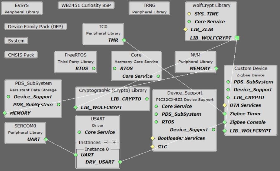
Cluster Configuration must be like the following figures .
-
Clusters selection
Clusters selection
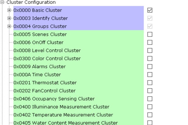
Figure 4-41. Custom flowRateMonitor cluster configuration-1 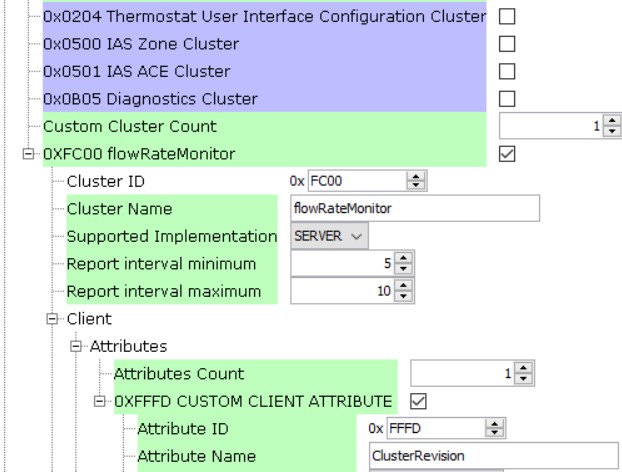
Custom flowRateMonitor cluster configuration-2 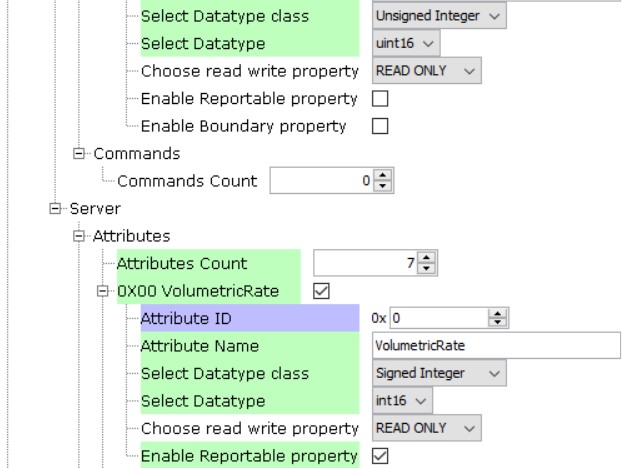
Figure 4-42. . Custom flowRateMonitor cluster configuration-3 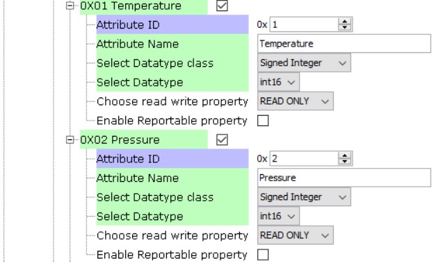
Figure 4-43. . Custom flowRateMonitor cluster configuration-4 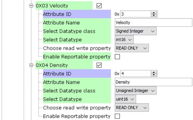
Figure 4-44. . Custom flowRateMonitor cluster configuration-5 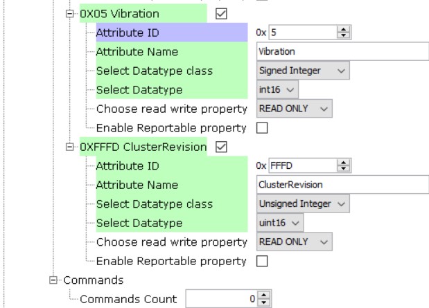
Generate code once MCC configurations are done.
Modify code mentioned in app_user_edits.c
Modify CS_UID in zigbeeAppDeviceSelect.h file, to make CS_UID in custom_cluster_server and custom_cluster_client two examples are not identical.
Clean and Build project.
.