
4.7.6 Zigbee Custom Device Example: Light Control with Occupancy Sensing
Introduction
Wireless_zigbee MCC component(Wireless-Drivers-Zigbee) provides device type as Custom Device, this allows user to customize the combination of clusters to build a Zigbee custom device.
Custom Device MCC Component
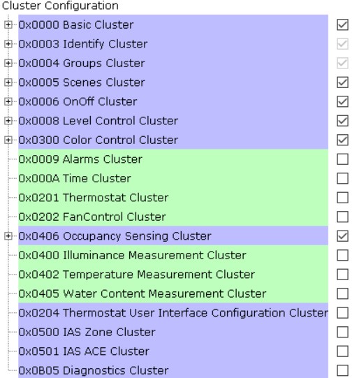
This application as a custom device example, it enables below 8 clusters to compose a custom device:
Basic cluster(ID: 0x0000)
Identify cluster(ID: 0x0003)
Groups cluster(ID: 0x0004)
Scenes cluster(ID: 0x0005)
OnOff cluster(ID: 0x0006)
Level Control cluster(ID: 0x0008)
Color Control cluster(ID: 0x0300)
Occupancy Sensing cluster(ID: 0x0406)
With this custom device, user can control lighting on off by the motion of occupancy sensor occupied or unoccupied.
This application as Zigbee router role needs work with another Zigbee coordinator (Combined Interface application).
Hardware Requirement
|
Tool |
Quantity |
|---|---|
|
WBZ451(or WBZ351) Curiosity Board |
2 |
|
Micro USB Cable |
2 |
|
Personal Computer |
1 |
|
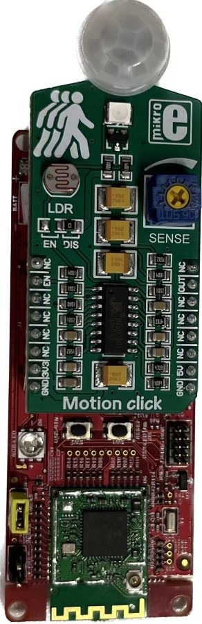
Motion Click board |
1 |
Motion click board add onto WBZ451 Curiosity board
SDK Setup
Gettting Started with Software DevelopmentSoftware Requirement
Programming the Precompiled Hex File or Application Example
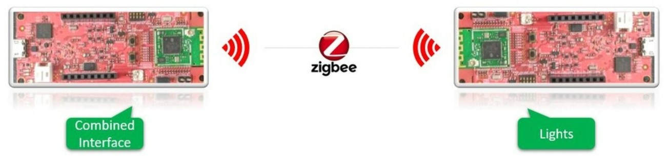
To run the demo, we need 2 devices. One is the Combined Interface(combinedInterface) and the other is custom Occupancy Light (occupancy_light).
-
One of WBZ451/WBZ351 Curiosity board is programmed with Combined Interface which act as Zigbee Gateway/Coordinator. Program the CI precompiled hex image by following steps on one curiosity board.
-
Another WBZ451/WBZ351 Curiosity board is programmed with occupancy_light application which can act as Zigbee Router. Follow the below steps for programming occupancy_light application on another curiosity board.
- Occupancy_light precompiled
Hex file is located in "<Harmony Content
Path>
\wireless_apps_pic32cxbz2_wbz45\apps\zigbee\custom_occupancy_light\hex"OR "<Harmony ContentPath>\wireless_apps_pic32cxbz3_wbz35\apps\zigbee\custom_occupancy_light\hex"folder - combinedInterface precompiled
Hex file is located in "<Harmony Content
Path>
\wireless_apps_pic32cxbz2_wbz45\apps\zigbee\combinedInterface\hex"OR "<Harmony Content Path>\wireless_apps_pic32cxbz3_wbz35\apps\zigbee\combinedInterface\hex"folder - Program two Curiosity boards with two precompiled hex files by following the steps mentioned in Programming A Device
Programming the Application using MPLABX IDE
-
Follow steps mentioned in of Running a Precompiled Example document
-
Open and program the Application Example “occupancy_light.x" located in "<Harmony Content Path>
\wireless_apps_pic32cxbz2_wbz45\apps\zigbee\custom_occupancy_light\firmware"or "<Harmony Content Path>\wireless_apps_pic32cxbz3_wbz35\apps\zigbee\custom_occupancy_light\firmware"using MPLABX IDE Open and program the Application Example “combinedInterface.x" located in "<Harmony Content Path>
\wireless_apps_pic32cxbz2_wbz45\apps\zigbee\combinedInterface\firmware" or "<Harmony Content Path>\wireless_apps_pic32cxbz3_wbz35\apps\zigbee\combinedInterface\firmware" using MPLABX IDE-
For more details on how to find the Harmony Content Path, refer to Installing the MCC Plugin Installing the MCC Plugin
Demo Description
The demo application demonstrates the Zigbee protocol functionality of PIC32CXBZ/WBZ family of devices and modules. It consists of a ZigBee 3.0 Coordinator and Router implemented as shown below:
|
Application |
Zigbee Logical Device Type |
Functionality |
|---|---|---|
| Combined Interface | Coordinator | Device capable of controlling and monitoring other devices. It is typically a mains-powered device like a personal computer |
| Custom Device (Occupancy Light) | Router | Is a lighting device that can be switched on/off by detecting occupancy sensor occupied or unoccupied. Lighting device other function like brightness & color control can be adjusted via the color commands. |
Zigbee device commissioning:
The Zigbee router i.e. Extended Lights can be commissioned and brought to the existing zigbee network formed by Zigbee coordinator i.e. Combined Interface or can create new zigbee Distributed network (if there is no nearby network).
Zigbee Light Control:
Extended light RGB LED can be controlled from Zigbee Gateway of the same network.
When the light status is changed the light change report will be sent to zigbee gateway through Zigbee communication.
Demo Steps
The Zigbee light can be connected to any Zigbee network.
Joining Light with WBZ451/WBZ351 Combined Interface (CI) Coordinator
Hardware & Software Setup
Supply power to WBZ451/WBZ351 Curiosity Board consisting of Combined Interface application by connecting a USB cable. Power Supply (PS) Green LED will turn on when connect to PC.
The application activity is shown as "Console Log" through on board UART-USB converter.
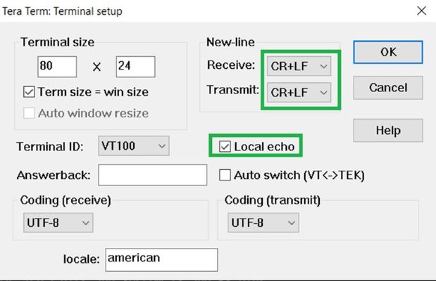
Open Terminal(eg: Tera Term) with the setup as shown below to look for these logs
On the PC side virtual COM port connection that corresponds to the board shall have following settings:
BAUD RATE: 115200 (as configured in SERCOM configuration)
PARITY: None
DATA BITS: 8
STOP BITS: 1
FLOW CONTROL: None
Additionally, local echo and sending line ends with line feeds shall be enabled in the PC serial terminal application.
Network Formation (Coordinator - (Combined Interface))
Follow the steps explained in Network Formation (Coordinator - (Combined Interface)) to open up the network in CI.
Commissioning (Router - Occupancy Light)
The Occupancy Lights can be connected to any Zigbee gateway (Combined interface running on WBZ451/WBZ351 Curiosity Board in the previous step).
Supply power to another WBZ451 Curiosity Board programmed with occupancy_light by connecting a USB cable. Power Supply (PS) Green LED will turn on when connect to PC.
Follow step 2 in "Hardware & Software Setup" for UART terminal Setup.
Input command : resetToFN and look for the below logs for successful joining with CI.
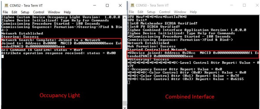
Success logs: When extended light successfully commissioned with Combined Interface below log will be seen.
Commissioning
Light Control by Occupancy Sensor Detection
RGB LED and Occupancy Sensor on WBZ451/WBZ351 curiosity board is tied with Zigbee functionality. The LED On Off can be controlled by motion of occupy or move away from the motion sensor on board.
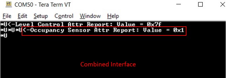
Occupy the motion sensor, RGB LED turns on. Light device reports Occupancy Sensor attribute value 0x1 to Combined Interface.
Report value 0x1 when occupying motion sensor
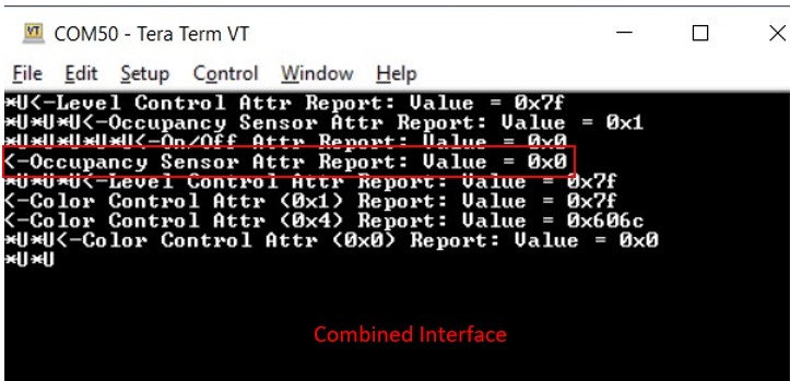
Move away from the motion sensor, RGB LED turns off, light device reports Occupancy Sensor attribute value 0 to Combined Interface.
Report value 0x0 when move away from motion sensor
The LED color and brightness can also be changed through Zigbee network using console commands, this is same function as ext_light application.
On Board Button Actions
When "User Button (SW2)" on WBZ451Curiosity board or "User Button 1(SW3)" on WBZ351 Curiosity board is pressed for more than 10sec, it can delete all the networking information and will bring the device to factory default state. This functionality is available in both combined interface and light devices.
Use Button to Simulate Occupancy Sensor
If enable macro _USE_BTN_SIMULATE_SENSOR in the example code, user can use “User Button(SW2)” on WBZ451 Curiosity board or "User Button 2(SW2)" on WBZ351 Curiosity board to simulate occupancy sensor if no motion click board available.
Note: with WBZ451 Curiosity board, if sensor simulation function enabled, "User Button(SW2)" is not available for reset to factory default function.
Creating Application Device Types From Scratch Using MCC
-
Follow steps in Generating project from MCC to create a new Zigbee project, add Zigbee component by device type, USART, SERCOM0, configure receiving pin for SERCOM0, and check configuration of following items:
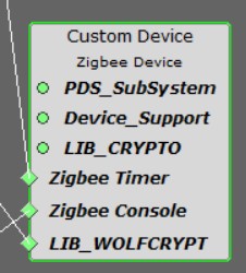
- Zigbee device type is selected as Custom Device.
- In Custom Device component, clusters to be supported are selected as following figure:
Figure 4-25. . Select clusters supported in the custom device
-
Add other components including APP_TIMER SERVICE and EIC. For WBZ451Curiosity board, need to add TC2 and TC3 to drive RGB LED. For WBZ351 Curiosity board, need to add RGB_LED_SERVICE. Also configure pin assignments for the board. Detailed configuration of these components and pin assignments can be referred as below figures:
Figure 4-26. . APP_TIMER_SERVICE configuration
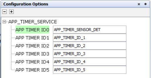
Figure 4-27. . EIC configuration for WBZ451Curiosity board
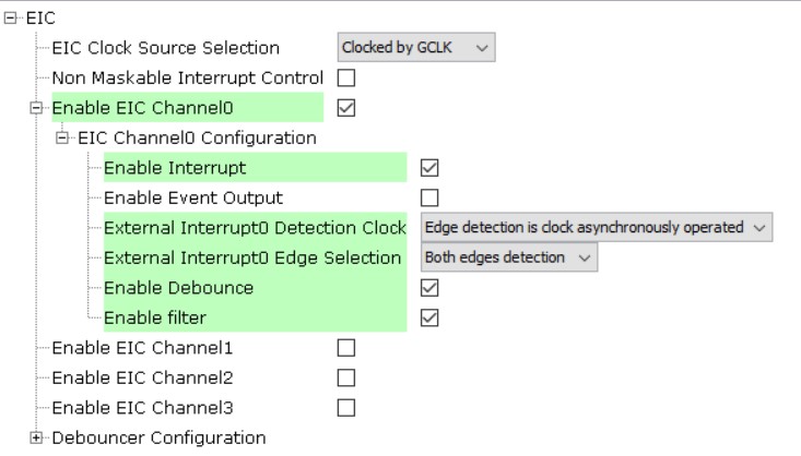
Figure 4-28. . EIC configuration for WBZ351 Curiosity board 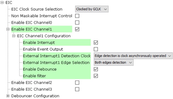
Figure 4-29. . TC2 configuration, only required by WBZ451 Curiosity board
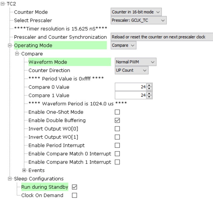
Figure 4-30. . TC3 configuration, only Required by WBZ451 Curiosity board 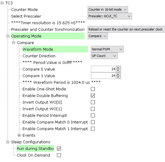
-
Pin assignment details:
Figure 4-31. . Pin assignment for WBZ451 Curiosity board -1
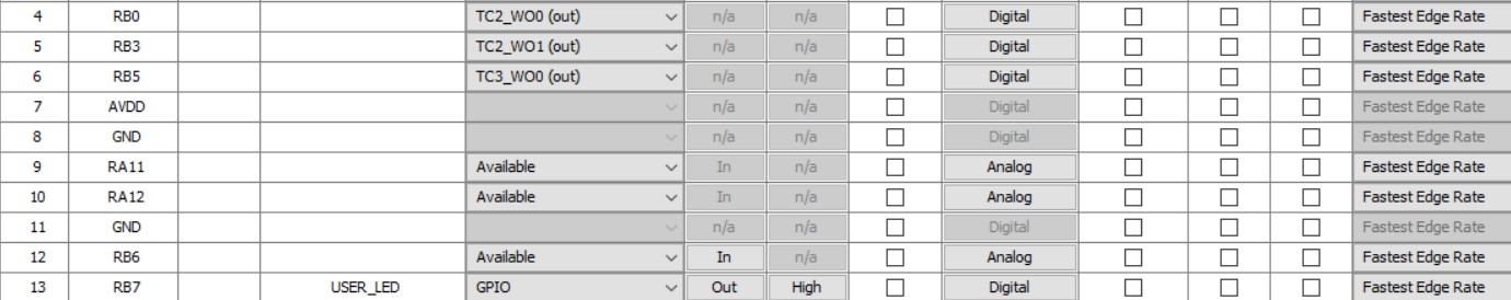
Figure 4-32. . Pin assignment for WBZ451 Curiosity board -2 
Figure 4-33. . Pin assignment for WBZ351 Curiosity board -1 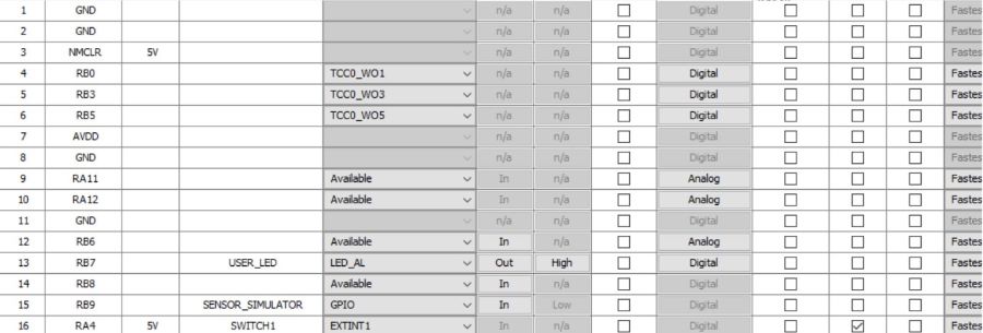
Figure 4-34. . Pin assignment for WBZ351 Curiosity board -2 
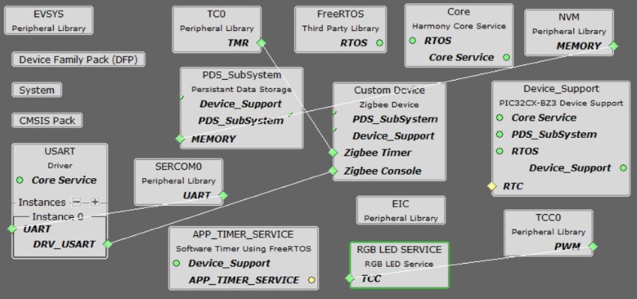
- After MCC configuration is done, projet graph should look like this:
Figure 4-35. . Project graph for WBZ451 Curiosity board
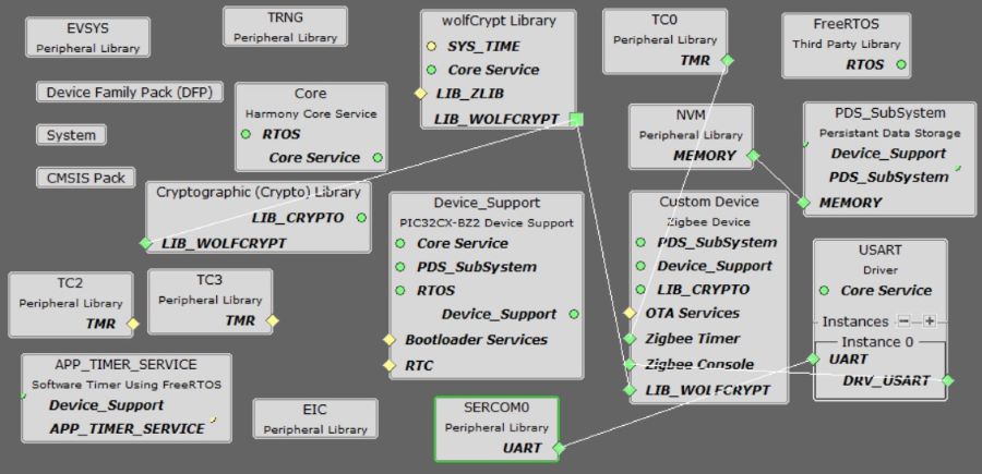
Figure 4-36. . Project graph for WBZ351 Curiosity board
Generate code once MCC configurations are done.
Modify code mentioned in app_user_edits.c.
Modify CS_UID in zigbeeAppDeviceSelect.h file, to make CS_UID is different from what defined for combinedInterface.
Manually add app_button_handler.c and app_button_handler.h files into project, this enables button press function and reletive handlers.
Manually add rgb_led.c and rgb_led.h files into project, this provides RGB LED driver code. This LED driver uses PWM function from TC2 and TC3.
There are some code added in files app.c, app.h, app_timer.c, these code are added to do sensor detection and set/clean occupancy sensing cluster attribute value, as well as print demo name and version information.
There are some code added in app_zigbee_handler.c, these code are added to control RGB LED when relative ZCL events coming.
To speed up occupancy value update when sensor detects change, need to add below code in file customOccupancySensingCluster.c, function void customOccupancySensingClusterInit(void):
customOccupancySensingClusterServerAttributes.occupancy.minReportInterval = 1;
This code enable occupancy attribute in occupancySensing cluster to report its value change in 1 second, the default is 10 second.
Clean and Build project.