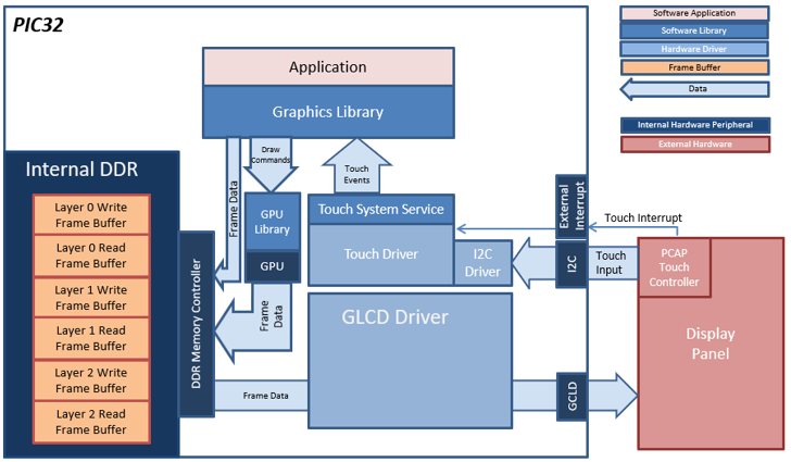
The aria_showcase application uses the aria graphics library to render graphics to the display. The graphics library draws the widgets and images to a frame buffer. The contents of the frame buffer are continuously transferred to refresh the contents of the LCD display. The application also features user touch input through the integrated touch screen on the display panel. Touch input from the touch controller goes through the I2C port, and the Input System Service acquires the touch input information from the Touch and I2C Drivers. The Input System Service sends touch events to the Graphics Library, which processes these events and updates the frame data accordingly.
Finally, the application uses the Timer System Service and driver to send timer events for Demo mode and to transition images in the Slideshow Demo at specified intervals.
The block diagram(s) below show the various software and hardware blocks used in this application.
In this configuration, the frame buffers are stored in the internal DDR memory. The DDR memory is large enough to allow 3 layers with double frame buffers. Double buffering eliminates the tearing effect since the contents of the write frame buffer are not shown in the display until the GFX library is done drawing on it. When the GFX library is done drawing on the write frame buffer, it is swapped with the read frame buffer in order to be shown on the display. The contents of the read frame buffer are transferred continuously by the Graphics LCD (GLCD) controller to the display panel.
This configuration also takes advantage of the DDR by pre-decoding some of the images to DDR as 32-bit RAW image assets. This allows faster image rendering since the images do not have to be decoded while rendering, and it uses the GPU to directly render or ‘blit’ the images to the frame buffer at a faster rate.
accordingly.
- Input system service and driver
- Time system service, timer-counter peripheral library and driver
- DMA System Service
- Low-Cost Controllerless (LCC) graphics driver
- I2C driver
- 16-bit RGB565 color depth support (65535 unique colors)
- JPEG and PNG images stored in internal flash
- UTF-8 and UTF-16 character font support
- Full multi-lingual font and localization (Chinese and English)
- Graphics Demo mode
- Graphics widgets: List wheel, Touch Test, Keypad, Slideshow
- Alpha-blending
In this configuration, the frame buffers are stored in the internal DDR memory. The DDR memory is large enough to allow 3 layers with double frame buffers. Double buffering eliminates the tearing effect since the contents of the write frame buffer are not shown in the display until the GFX library is done drawing on it. When the GFX library is done drawing on the write frame buffer, it is swapped with the read frame buffer in order to be shown on the display. The contents of the read frame buffer are transferred continuously by the Graphics LCD (GLCD) controller to the display panel.
This configuration also takes advantage of the DDR by pre-decoding some of the images to DDR as 32-bit RAW image assets. This allows faster image rendering since the images do not have to be decoded while rendering, and it uses the GPU to directly render or ‘blit’ the images to the frame buffer at a faster rate.
accordingly.
• GLCD display controller and NANO 2D GPU
• 32-bit RGBA Color Mode Frame Buffer in DDR memory
• Input system service and touch driver
• Time system service, timer-counter peripheral library and driver
• RLE compressed RGB image in internal flash
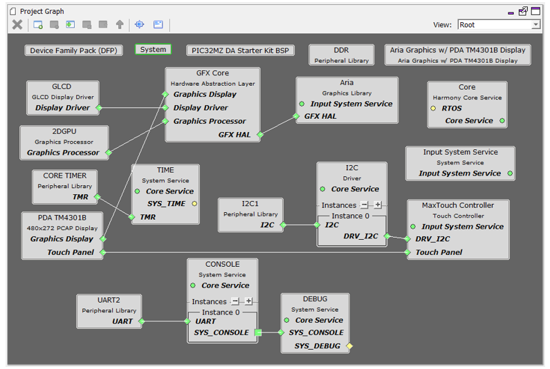
The Project Graph diagram shows the Harmony components that are included in this application. Lines between components are drawn to satisfy components that depend on a capability that another component provides.
Adding the “PIC32MZ DA Starter Kit BSP” and “Aria Graphics w/ PDA TM4301B Display” Graphics Template component into the project graph will automatically add the components needed for a graphics project and resolve their dependencies. It will also configure the pins needed to drive the external peripherals like the display and the touch controller.
The I2C Baud Rate for the I2C1 component to 1,000,000 Hz.

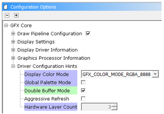
Enable Double Buffer Mode in GFX Core
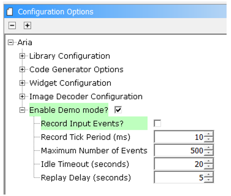
In the Aria component, demo mode is enabled
The parent directory for this application is gfx_apps/apps/aria_showcase. To build this application, open the gfx_apps/apps/aria_showcase/firmware/aria_oc_mzdas_sk_meb2_tm4301b.X project file in MPLABX IDE that corresponds to the hardware configuration.
The following table lists configuration properties:
|
Project Name |
BSP Used |
Graphics Template Used |
Description |
|
PIC32MZ DA Starter Kit |
Aria Graphics w/ PDA TM4301b Display |
Aria GFX on PIC32MZ DA with Internal DDR Starter Kit, MEBII and PDA TM4301b Display |
 Important! Important! |
This application may contain custom code that is marked by the comments // START OF CUSTOM CODE ... and // END OF CUSTOM CODE. When using the MPLAB Harmony Configurator to regenerate the application code, use the "ALL" merging strategy and do not remove or replace the custom code. |
On the MEB II, the EBIOE and LCD_PCLK (J9) must be jumpered. A connection establishes the GLCD's pixel clock output timing. The external SRAM memory on the board is disabled. The J9 jumper is located on the bottom of the MEB II board, beneath where the starter kit is plugged into the board. Refer to the following figure for the exact location.
![]()
Connect the PIC32MZ DA Starter Kit to the MEB II board

Power up the board by connecting the power adapter to J3 power connector on the MEB II board or a powered USB cable to the USB DEBUG
port on the Starter Kit board
Upon boot-up, the application displays the animation Splash Screen, which shows an animated splash bar while blending in the MPLAB Harmony and Microchip PIC32 logos, as shown in the following figure.
When power-on is successful, the application Home Screen will be displayed.
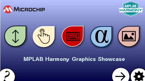
On the Home Screen, touching the large icons will open various screens that demonstrate the functionality of the widgets in the Aria graphics library.
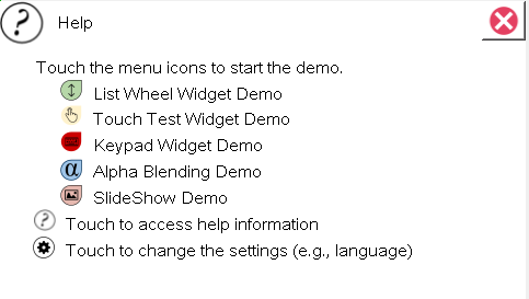
Touching the Help (?) button on the lower left corner of each screen will show help information similar to the following figure.
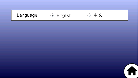
The Settings Screen shows an option to switch the language between English and Simplified Chinese and demonstrates the Aria string library’s capability to support multi-lingual fonts and symbols.
The List Wheel Widget Demo screen shows an example on how the list wheel widget can be used to provide UI controls for changing the time. The following figures show the List Wheel Widget Demo screen on PIC32MZ DA and PIC32MZ EF, respectively.
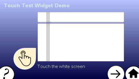
The Touch Test Widget Demo screen shows the touch screen functionality.

When the white active area of the Touch Test Widget is touched, intersecting horizontal and vertical lines indicate the touch points.
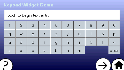
The Keypad Widget Demo Screen shows how the keypad and text entry widgets can be used to provide an interface for obtaining user text input. Touching the Text Field widget will show the Keypad for typing the text input.
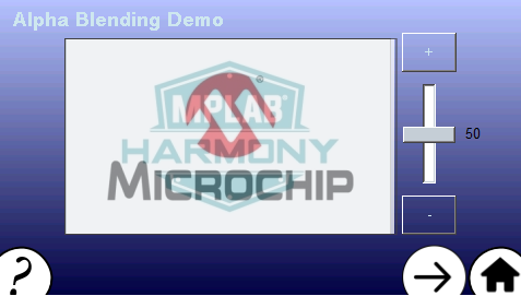
The Alpha Blending Demo screen shows the alpha blending capabilities of the Aria User Interface Library. The demonstration features two JPEG images that are alpha blended on top of each other. The (+) and (-) buttons and the slider widget on the right side of the images provides a way to change the alpha amounts.
Alpha blending at 50%
Alpha blending at 100%

Alpha blending at 0%

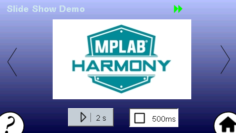
The Slide Show Demo Screen features the slide show widget being used to transition between several JPEG images using the available controls.
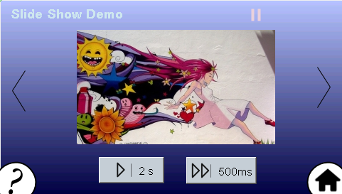
Touching the LEFT (<) and RIGHT (>) buttons manually transitions through the list of images. Touching the PLAY (|>) and FAST-FORWARD (|>>) buttons will automatically transition the images at 2s and 500ms intervals, respectively. The transitions are triggered using events from the Timer System Service.
The following figure shows Slide Show widget in Play mode.
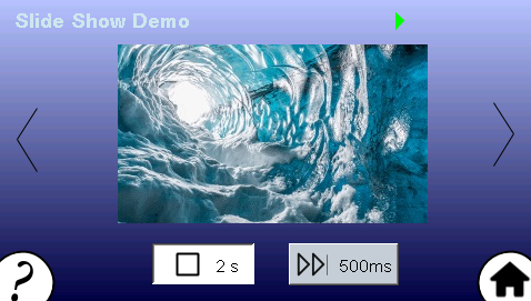
The following figure shows the Slide Show widget in FAST-FORWARD mode.
Help information for the demonstration screens can be accessed by touching the (?) button on the lower left corner of each screen. Touching the HOME button on the lower right corner takes the application back to the Home Screen.
|
MPLAB® Harmony Graphics Suite Applications
|