![]()
FLEXCOM USART blocking
This example application shows how to use the flexcom module in USART mode.
Description
This application configures the flexcom peripheral in USART mode and performs read and write operation in a blocking manner. The CPU polls the peripheral register continuously to manage the transfer. It receives a line of characters from the terminal window and echoes them back.
Downloading and building the application
To clone or download this application from Github, go to the main page of this repository and then click Clone button to clone this repository or download as zip file. This content can also be downloaded using content manager by following these instructions.
Path of the application within the repository is apps/flexcom/usart/flexcom_usart_echo_blocking/firmware .
To build the application, refer to the following table and open the project using its IDE.
| Project Name | Description |
|---|---|
| sam_a5d2_xult.X | MPLABX project for SAMA5D2 Xplained Ultra Evaluation Kit |
Setting up AT91Bootstrap loader
To load the application binary onto the target device, we need to use at91bootstrap loader. Refer to the at91bootstrap loader documentation for details on how to configure, build and run bootstrap loader project and use it to bootstrap the application binaries.
Setting up the hardware
The following table shows the target hardware for the application projects.
| Project Name | Board |
|---|---|
| sam_a5d2_xult.X | SAMA5D2 Xplained Ultra Evaluation Kit |
Setting up SAMA5D2 Xplained Ultra Evaluation Kit
Addtional hardware required
Setting up the board
- Short jumper JP2 (DEBUG_DIS)
- Connect the Debug USB port on the board to the computer using a micro USB cable
-
Connect USB UART click board to SAM A5D2 Xplained Ultra board as per below Pin Connections
SAM A5D2 Xplained Ultra board Pins USB UART click board Pins F0_TXD, J22 connector RX F0_RXD, J22 connector TX PIN 20, XPRO EXT2 connector 3.3V PIN 19, XPRO EXT2 connector GND - Connect the Mini USB connector on the USB UART click board to the computer using a Mini USB cable
Running the Application
- Build the application using its IDE
- Open the Terminal application (Ex.:Tera term) on the computer.
- Connect to the EDBG/Jlink Virtual COM port and configure the serial settings as follows:
- Baud : 115200
- Data : 8 Bits
- Parity : None
- Stop : 1 Bit
- Flow Control : None
-
The console displays the following message
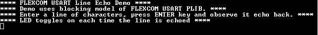
- Type a line of characters and press the Enter key (NOTE: Number of characters entered before pressing enter key must be less than 256))
- Entered line will be echoed back and the LED is toggled
-
The following table provides the LED names
Board LED Name SAMA5D2 Xplained Ultra Evaluation Kit RGB_LED(Green)