![]()
RTCC alarm interrupt
This example application shows how to use the RTCC to configure the time and generate the alarm.
Description
This example application shows how to setup RTCC time and configure alarm using the RTCC Peripheral Library. The application sets up an alarm to be generated every day at a specified time. A message is sent via the Virtual COM port on the alarm trigger.
Downloading and building the application
To clone or download this application from Github, go to the main page of this repository and then click Clone button to clone this repository or download as zip file. This content can also be downloaded using content manager by following these instructions.
Path of the application within the repository is apps/rtcc/rtcc_alarm/firmware .
To build the application, refer to the following table and open the project using its IDE.
| Project Name | Description |
|---|---|
| pic32mz_w1_curiosity.X | MPLABX project for PIC32MZ W1 Curiosity Board |
Setting up the hardware
The following table shows the target hardware for the application projects.
| Project Name | Board |
|---|---|
| pic32mz_w1_curiosity.X | PIC32MZ W1 Curiosity Board |
Setting up PIC32MZ W1 Curiosity Board
- Connect the Debug USB port on the board to the computer using a micro USB cable
- On the GPIO Header (J207), connect U1RX (PIN 13) and U1TX (PIN 23) to TX and RX pin of any USB to UART converter (for eg: USB UART click board)
Running the Application
- Open the Terminal application (Ex.:Tera term) on the computer
- Connect to the “USB to UART” COM port and configure the serial settings as follows:
- Baud : 115200
- Data : 8 Bits
- Parity : None
- Stop : 1 Bit
- Flow Control : None
- Build and Program the application project using its IDE
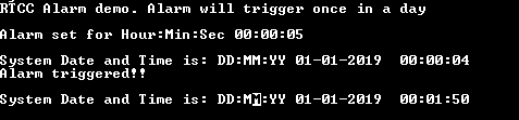
- Console output will be as given below in the beginning:

-
Once alarm triggers, following will be console output: