![]()
DMT timeout
This example application shows how the deadman timer resets by not clearing the deadman timer counter on switch press.
Description
This example application shows, how DMT PLIB resets the device by not clearing the Deadman timer counter on every user switch press. This application sets up the DMT to reset the device after DMT counter overflows. This application also sets up the CoreTimer to blink an LED and to clear DMT counter before device reset happens. When user presses the switch, it forces the device to wait an infinite loop to emulate a deadlock condition. As a result, it will triggers the deadman counter overflows the bounded value and device will reset due to this deadman timeout.
Downloading and building the application
To clone or download this application from Github, go to the main page of this repository and then click Clone button to clone this repository or download as zip file. This content can also be downloaded using content manager by following these instructions.
Path of the application within the repository is apps/dmt/dmt_timeout/firmware .
To build the application, refer to the following table and open the project using its IDE.
| Project Name | Description |
|---|---|
| pic32mz_w1_curiosity.X | MPLABX project for PIC32MZ W1 Curiosity Board |
Setting up the hardware
The following table shows the target hardware for the application projects.
| Project Name | Board |
|---|---|
| pic32mz_w1_curiosity.X | PIC32MZ W1 Curiosity Board |
Setting up PIC32MZ W1 Curiosity Board
- Connect the Debug USB port on the board to the computer using a micro USB cable
- On the GPIO Header (J207), connect U1RX (PIN 13) and U1TX (PIN 23) to TX and RX pin of any USB to UART converter (for eg: USB UART click board)
Running the Application
- Open the Terminal application (Ex.:Tera term) on the computer
- Connect to the EDBG Virtual COM port and configure the serial settings as follows:
- Baud : 115200
- Data : 8 Bits
- Parity : None
- Stop : 1 Bit
- Flow Control : None
- Build and Program the application project using its IDE
-
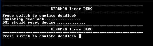
Console displays the following message:

- The deadman timer is fed periodically using Core Timer (CoreTimer) to prevent the DMT reset and the LED is toggled
- Press the switch to put the system in deadlock (LED should stop blinking)
-
Following table provides switch and LED name
Board Switch name LED name PIC32MZ W1 Curiosity Board SW1 RED LED (D202) -
Console displays the following message:
- The DMT will reset the device with in 12 seconds and the demonstration should restart