Configuring the Hardware
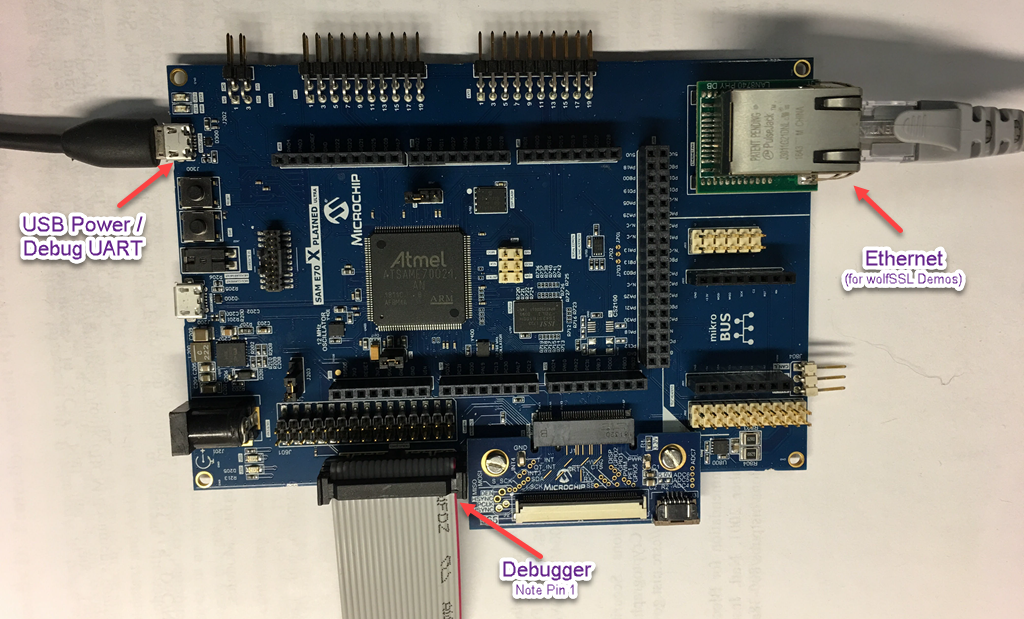
Refer to the following image for an illustration for where to connect the cables to.

- Connect the 20 pin debugger cable to the DEBUG SWD port. Note that Pin 1 (red) is closest to the mikro BUS label on the board
- (For the wolfSSL demonstrations) connect an Ethernet cable to the Ethernet Port
- Connect a Micro-USB B cable to the DEBUG USB port