Configuring the Hardware
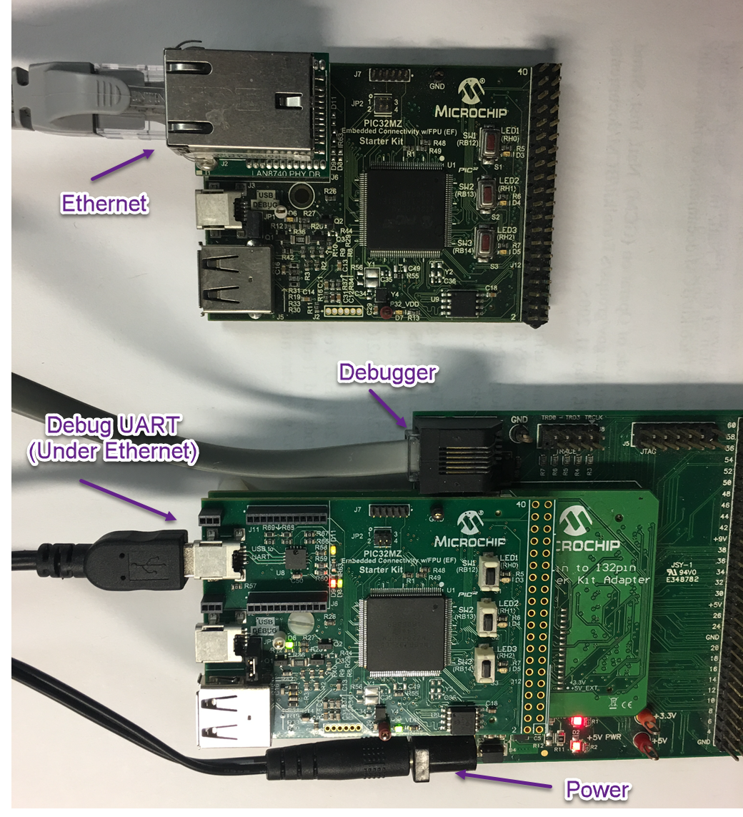
Refer to the following image for an illustration for where to connect the cables to.
- Connect the 168 pin to 132 pin Starter Kit Adapter board to the Starter Kit I/O Expansion Board, optionally use a nylon nut and bolt to secure the two boards together
- Connect the PIC32MZ Extended Connectivity w/FPU (EF) Starter kit to the 168 pin to 132 pin Starter Kit Adapter board, optionally use a nylon nut and bolt to secure the two boards together
- Connect the RealICE, or ICD to the RJ-11 port on the Starter Kit I/O Expansion Board
- Connect a USB Mini-b (5 pin) cable to the DEBUG USB port
- (For the wolfSSL demonstrations) connect an Ethernet cable to the Ethernet Port
- Connect the 9V power supply to the Starter Kit I/O Expansion Board