
1.4.2 PIC32MZ Embedded Graphics with Stacked DRAM (DA) Starter Kit (Crypto): Building and Running the QSPI Flash Bootloader applications
Downloading and building the application
To clone or download this application from Github,go to the main page of this repository and then click Clone button to clone this repo or download as zip file. This content can also be download using content manager by following these instructions
Path of the application within the repository is apps/qspi_flash_bootloader/
To build the application, refer to the following table and open the project using its IDE.
Bootloader Application
| Project Name | Description |
|---|---|
| bootloader/firmware/pic32mz_das_sk.X | MPLABX Project for PIC32MZ Embedded Graphics with Stacked DRAM (DA) Starter Kit (Crypto) |
Programmer application
| Project Name | Description |
|---|---|
| app_programmer/firmware/pic32mz_das_sk.X | MPLABX Project for PIC32MZ Embedded Graphics with Stacked DRAM (DA) Starter Kit (Crypto) |
Setting up PIC32MZ Embedded Graphics with Stacked DRAM (DA) Starter Kit (Crypto)
Connect a micro USB cable to the UART-USB port J5
For programming, connect a micro USB cable to the USB Debug port J19
Setting up the host script
Refer to UART Host Script Help for setting up the uart_host.py utility used to send the application binary from host PC
There will be no reset command sent from host after programming by default.
Reboot command has to be sent separately only after successful programming to trigger bootloader from programmer application
Running the Application
Open the bootloader project bootloader/firmware/pic32mz_das_sk.X in the IDE
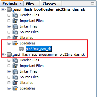
Make sure that the app_programmer/firmware/pic32mz_das_sk.X is added as a loadable project to bootloader application
As the QSPI Flash memory may not have any valid binary required by bootloader for the first time, Adding the app_programmer as loadable allows MPLAB X to create a unified hex file and program both these applications in their respective memory locations based on their linker script configurations
Build and program the bootloader application using the IDE
Once programming is done bootloader starts execution and directly jumps to application space to run the programmer application
LED3 starts blinking indicating that the programmer application is running
Open the programmer application project app_programmer/firmware/pic32mz_das_sk.X in the IDE
Update app_programmer/firmware/src/config/pic32mz_das_sk/user.h to use LED2 instead of LED3 as below
#define LED_TOGGLE() LED2_Toggle()
Clean and Build the project to generate the binary (Do not program the binary)
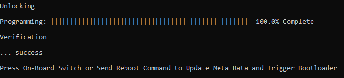
Run the uart_host.py from command prompt to program the updated programmer application binary in QSPI Flash memory
python <harmony3_path>/bootloader_apps_serial_memory/tools/uart_host.py -v -i <COM PORT> -d pic32mz -a 0x9D000000 -f <harmony3_path>/bootloader_apps_serial_memory/apps/qspi_flash_bootloader/app_programmer/firmware/pic32mz_das_sk.X/dist/pic32mz_das_sk/production/pic32mz_das_sk.X.production.binFollowing snapshot shows output of successfully programming the programmer application
LED3 should still be blinking
Run the uart_host.py from command prompt to send a Reboot command. This command Updates MetaData and triggers Bootloader to program the updated binary from QSPI Flash to Internal Flash
python <harmony3_path>/bootloader_apps_serial_memory/tools/uart_host.py -v -i <COM PORT> -r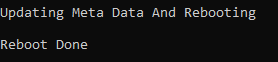
Once Firmware Update is successful LED2 should start blinking indicating updated programmer application running
If there was any error you may need to power cycle the device to retry firmware upgrade
Update app_programmer/firmware/src/config/pic32mz_das_sk/user.h to revert to LED3 from LED2 as below
#define LED_TOGGLE() LED3_Toggle()
Clean and Build the project to generate the binary (Do not program the binary)
Repeat Step 8-9.
You should see LED2 still blinking
Press the Switch SW1 to Update MetaData and trigger Bootloader to program the updated binary from QSPI Flash to Internal Flash
Once Firmware Update is successful LED3 should start blinking indicating updated programmer application running
If there was any error you may need to power cycle the device to retry firmware upgrade
Additional Steps (Optional)
To bootload any other application refer to Application Configurations
Note that this application should have programming capabilities to QSPI Flash Memory
Once done repeat the applicable steps mentioned in Running The Application