1.2.3.2 Bootloader linker configurations for CORTEX-M based MCUs
Linker configurations for the UART, I2C and CAN Bootloaders
Bootloader library uses a custom linker script which is generated through MCC
The values populated in the linker script are based on the Bootloader component MCC configurations
Bootloader is configured to run from RAM in this linker script to achieve simultaneous Flash memory write and reception of the next block of data.
Note: The below sections provides overview of changes done to bootloader linker scripts when compared to default linker script. The <bootloader_start> address and <bootloader_length> may vary based on the specific device used
#define ROM_START <bootloader_start>

/* Bootloader size is calculated with below criteria with optimization level -O2
 * bootloader size = Minimum Flash Erase Size Or actual bootloader ELF size
                     (Rounded of to nearest erase boundary) whichever is
                     greater.
 */
#define ROM_SIZE  <bootloader_length>

/* Bootloader Trigger pattern needs to be stored in starting <trigger_len> Bytes
 * of Ram by the application if it wants to run bootloader at startup without any
 * external trigger.
 * Example:
 *     ram[0] = 0x5048434D;
 *     ram[1] = 0x5048434D;
 *     ....
 *     ram[n] = 0x5048434D;
 */
#define RAM_START (<ram_start> + <trigger_len>)

#define RAM_SIZE  (<ram_length> - trigger_len)

MEMORY
{
  rom (rx) : ORIGIN = ROM_START, LENGTH = ROM_SIZE
  ram (rwx) : ORIGIN = RAM_START, LENGTH = RAM_SIZE
}

SECTIONS
{
    /*
     * Configure to place the vector table in Flash but to be run from RAM
     */
    .vectors :
    {
        . = ALIGN(4);
        _sfixed = .;
        KEEP(*(.vectors .vectors.*))
    } > ram AT > rom

    .text :
    {
        . = ALIGN(4);
        ....
        ....
        . = ALIGN(4);
        _efixed = .;            /* End of text section */
    } > rom

    ....
    ....

    . = ALIGN(4);
    _etext = .;

    /* Locate text/rodata in special data section to be copied to RAM
       in startup sequence. */
    .data :
    {
        . = ALIGN(4);
        __data_start__ = .;
        _sdata = .;
        *(.dinit)
        *(.text)
        *(.text.*)
        *(.rodata)
        *(.rodata.*)
        . = ALIGN(4);
        __data_end__ = .;
        _edata = .;
    } > ram AT > rom

    ....
}
Custom startup file for UART, I2C and CAN Bootloaders
To reduce the size of the binary these bootloaders make use of custom startup file which is generated by MCC
This startup file places only the Reset handler in vector table instead of populating all the device vectors there by reducing the size of final .vector section
This startup file also copies the entire bootloader code placed in .data section above from flash to RAM as it is built to run from RAM
/* Declaration of Reset handler (may be custom) */
void __attribute__((noinline)) Reset_Handler(void);

__attribute__ ((used, section(".vectors")))
void (* const vectors[])(void) =
{
  &_ram_end_,
  Reset_Handler,
};

...
...

/* Linker-defined symbols for data initialization. */
extern uint32_t _sdata, _edata, _etext;
extern uint32_t _sbss, _ebss;

void __attribute__((noinline, section(".romfunc.Reset_Handler"))) Reset_Handler(void)
{
    uint32_t *pSrc, *pDst;;

    pSrc = (uint32_t *) &_etext; /* flash functions start after .text */
    pDst = (uint32_t *) &_sdata;  /* boundaries of .data area to init */

    /* Copy code from flash to RAM using .data section */
    while (pDst < &_edata)
        *pDst++ = *pSrc++;

    /* Init .bss */
    pDst = &_sbss;
    while (pDst < &_ebss)
      *pDst++ = 0;

....
....
}
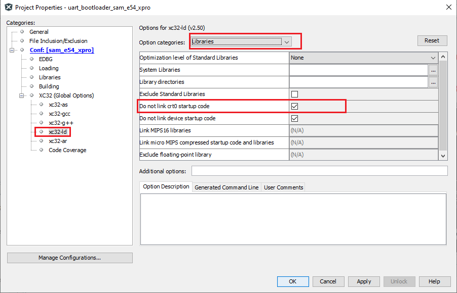
MPLAB X Setting for UART, I2C and CAN Bootloaders
Below MPLAB X option is enabled by MCC for these bootloaders to remove the XC32 crt0 startup code
By disabling this crt0 startup code we further reduce the size as it removes the default initialization mechanism code by XC32.

