
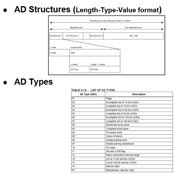
3.1.2.10 Path Loss Feature in Legacy Advertisements
Getting Started with Peripheral Building Blocks
BLE Sleep Mode Legacy Advertisements
Introduction
This document will help users to enable the Path Loss feature with BLE Advertisements on WBZ451 Curiosity board using the MPLAB Code Configurator(MCC)
The path loss is defined as the difference between the remote transmit power level and the average local RSSI measurement for the connection. In other words, Path loss refers to the attenuation or reduction in signal strength as it travels through the wireless channel from the transmitter (BLE device) to the receiver.
Path loss monitoring is a crucial feature in BLE, allowing for real-time assessment of signal strength and providing valuable insights for connection management.
Users can choose to just run the precompiled Application Example hex file on the WBZ451 Curiosity Board and experience the demo or can go through the steps involved in developing this Application from scratch
It is recommend to follow the examples in order, by learning the basic concepts first and then progressing to the more advanced topics.
Understanding Path Loss
Path Loss Zones
BLE path loss monitoring divides signal strength into specific zones to facilitate effective management. The core path loss zones are:
- Low Zone
- Middle Zone
- High Zone
The BLE Controller continuously evaluates path loss and notifies the Host when it transitions between these zones, based on predefined boundaries.

Calculating Path Loss
Path loss is determined as the difference between the remote transmit power level (the power at which the remote BLE device transmits) and the average local Received Signal Strength Indication (RSSI) measurement for the connection.
Zone Transition Criteria
- Transition to a Higher Zone: Path loss becomes greater than or equal to the upwards boundary when moving to a higher zone.
- Transition to a Lower Zone: Path loss becomes less than or equal to the downwards boundary when moving to a lower zone.
To prevent frequent zone switching, some hysteresis is provided. The upwards boundary should be greater than or equal to the downwards boundary, ensuring a smooth transition.
Correlation with Distance:
Path loss often correlates with the distance between BLE devices. A higher zone may indicate that the peer BLE device has moved farther away. This information can be invaluable for various applications, such as proximity detection and device localization.
Path Loss Measurement
- Power Control Request Procedure
The Power Control Request procedure involves periodically requesting the remote BLE device to provide its transmit power level. Combining this information with local RSSI measurements enables the calculation of path loss.
- Power Change Indication Procedure
The Power Change Indication procedure informs the Controller when the remote BLE device changes its transmit power level. This can occur due to adaptive power management or other factors. Upon receiving a power change indication, the Controller updates its path loss calculations accordingly.
Power Control Request procedure in context of path loss monitoring
The Power Control Request procedure is a critical component of path loss monitoring in Bluetooth Low Energy (BLE). This procedure enables the measurement of the remote transmit power level, which is essential for calculating path loss accurately.

Practical Applications
- Proximity Detection: Path loss data can be used to estimate the distance between BLE devices accurately. This is especially useful for applications such as asset tracking, location-based services, and contact tracing.
- Adaptive Power Management: Knowledge of path loss allows the Controller to dynamically adjust the transmit power level. This optimization helps conserve energy while maintaining a stable connection.
- Connection Maintenance: Path loss notifications serve as early warnings of degrading connections due to increasing path loss. This can trigger actions like reconfiguration or re-establishment of the connection to maintain service quality.
- Interference Mitigation: In environments with substantial interference, path loss monitoring helps identify deteriorating signal quality. This early detection enables the implementation of countermeasures, such as channel hopping or adjusting transmission parameters.
Recommended Reading
Hardware Requirement
| Tool | Qty |
|---|---|
| WBZ451 Curiosity Board | 2 |
| Micro USB cable | 2 |
SDK Setup
Software Requirement
Programming the precompiled hex file or Application Example
Programming the hex file using MPLABX IPE
-
Precompiled Hex file is located in "<Harmony Content Path>\wireless_apps_pic32cxbz2_wbz45\apps\ble\building_blocks\peripheral\Legacy_ADV_Pathloss\dist\default\production\" folder
-
Follow the steps mentioned hereNote: Ensure to choose the correct Device and Tool information
Programming the Application using MPLABX IDE
-
Follow steps mentioned in of Running a Precompiled Example document
-
Open and program the Application Example
"Legacy_ADV_Pathloss.X.production.x" located in "<Harmony Content
        Path>\wireless_apps_pic32cxbz2_wbz45\apps\ble\building_blocks\peripheral\Legacy_ADV_Pathloss\firmware"
using MPLABX IDE
For more details on how to find the Harmony Content Path, refer to Installing the MCC Pluggin
Demo Description
This application example implements the path loss feature into an peripheral legacy advertisement application. The testing of this application is done by connecting the path loss feature included peripheral legacy application to an Central connection application. After successfully connection, at the peripheral application serial console, the path loss and zone will be updated frequently.
Testing
- Connect the first WBZ451 Curiosity board to PC, program the central connection application. The central connection application once booted will start scanning and upon finding the device with BT Address A6A5A4A3A2A1 will initiate a connection.
- Connect the second WBZ451 Curiosity board to PC, program the path loss peripheral legacy advertisement application . Open Dockligth Scripting @ (Speed: 115200, Data: 8-bit, Parity: none, stop bits: 1 bit, Flow control: none). Reset the board. Upon reset, "Advertising" message is displayed on the TeraTerm.

Developing the Application from Scratch using MPLAB Code Configurator
Create a new MCC Harmony Project. For more details, refer to 2.5 Creating a New MCC Harmony Project.
Import component configuration: This step helps users setup the basic components and configuration required to develop this application. The imported file is of format .mc3 and is located in the path <Harmony Content Path>\wireless_apps_pic32cxbz2_wbz45\apps\ble\building_blocks\peripheral\legacy_ADV_Pathloss\firmware\legacy_ADV_Pathloss.X. Users must follow the instructions mentioned 14.3 Importing Existing App Example Configuration to import the component configuration.
Accept Dependencies or satisfiers, select Yes
- Verify if the Project Graph window has all the expected configuration
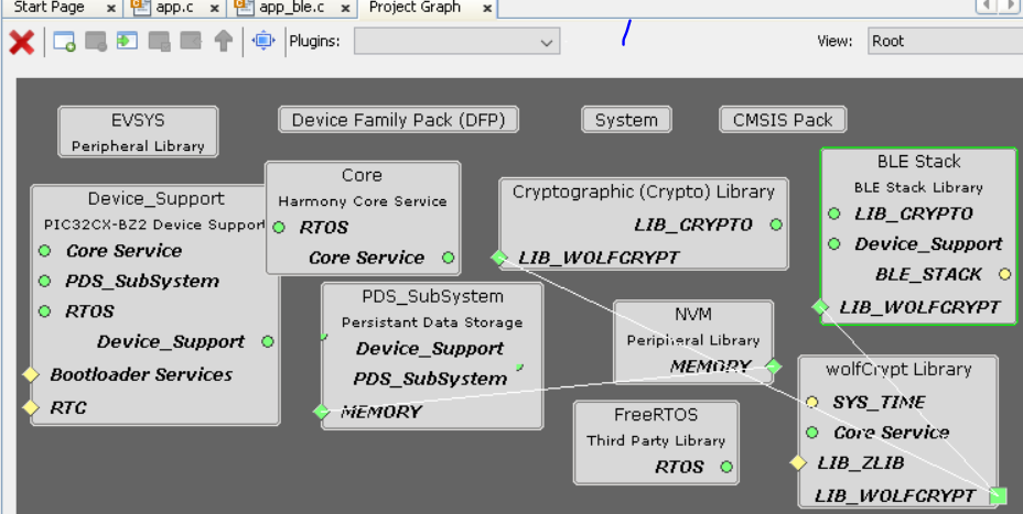
- Generate the code.
Files and Routines Automatically generated by the MCC
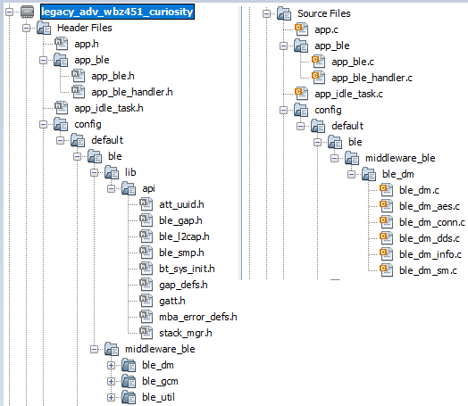
After generating the program source from MCC interface by clicking Generate Code, the BLE configuration can be found in the following project directories
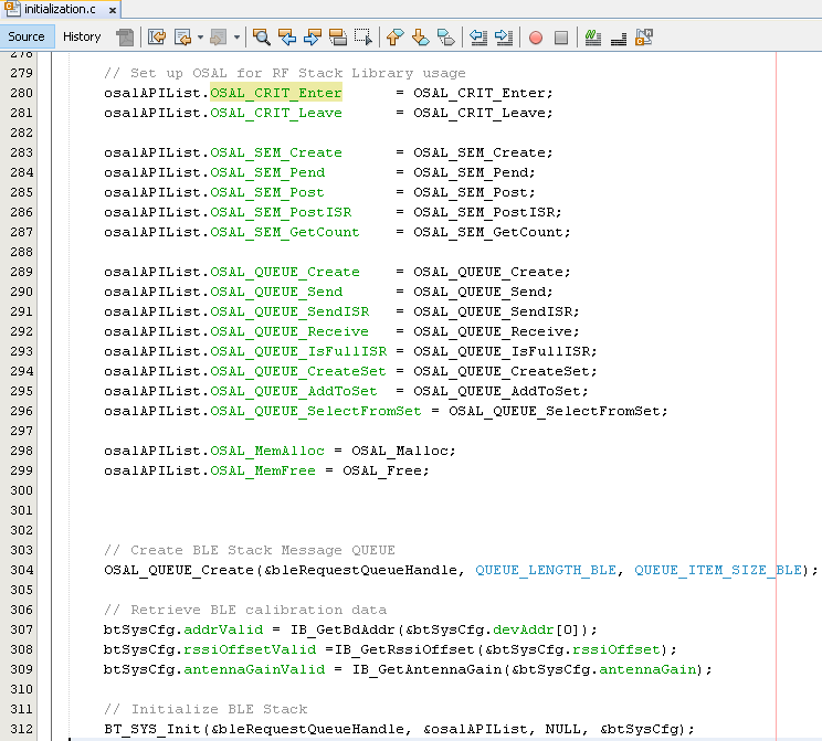
The OSAL, RF System, BLE System initialization routine executed during program initialization can be found in the project files. This initialization routine is automatically generated by the MCC
The BLE stack initialization routine excuted during Application Initialization can be found in project files. This intitialization routine is automatically generated by the MCC. This call initializes and configures the GAP, GATT, SMP, L2CAP and BLE middleware layers.
Autogenerated, adverisement Data Format
| Source Files | Usage |
|---|---|
| app.c | Application State machine, includes calls for Initialization of all BLE stack (GAP,GATT, SMP, L2CAP) related component configurations |
| app_ble.c | Source Code for the BLE stack related component configurations, code related to function calls from app.c |
| app_ble_handler.c | All GAP, GATT, SMP and L2CAP Event handlers |
Header Files
-
ble_gap.h: This header file contains BLE GAP functions and is automatically included in the app.c file
Function Calls
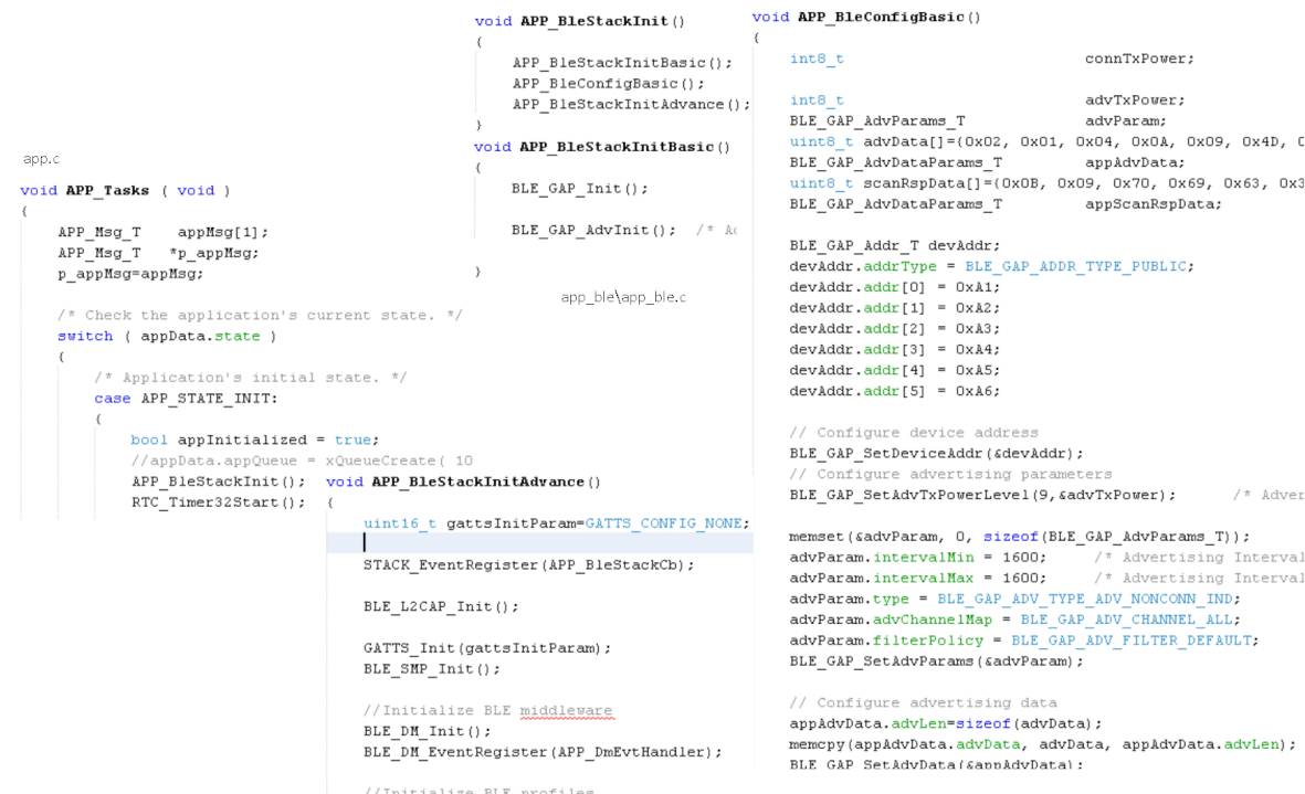
MCC generates and adds the code to initialize the BLE Stack GAP, GATT, L2CAP and SMP in APP_BleStackInit() function
-
APP_BleStackInit() is the API that will be called inside the Applications Initial State -- APP_STATE_INIT in app.c
User Application Development
Include
-
User action is required as mentioned in User Action
-
definitions.hin all the files where UART will be used to print debug information
Set PUBLIC Device Address
-
BLE_GAP_SetDeviceAddr(&devAddr);
This API can be called in APP_BleConfig() located in file app_ble.c
    BLE_GAP_Addr_T devAddr;
    devAddr.addrType = BLE_GAP_ADDR_TYPE_PUBLIC;
    devAddr.addr[0] = 0xA1;
    devAddr.addr[1] = 0xA2;
    devAddr.addr[2] = 0xA3;
    devAddr.addr[3] = 0xA4;
    devAddr.addr[4] = 0xA5;
    devAddr.addr[5] = 0xA6;

    // Configure device address
    BLE_GAP_SetDeviceAddr(&devAddr);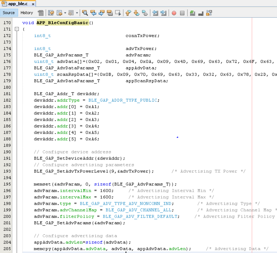
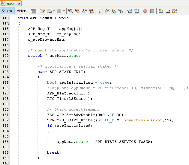
Start Advertisement
-
BLE_GAP_SetAdvEnable(0x01, 0);
This API is called in the Applications initialstate - APP_STATE_INIT in app.c
Users can exercise various other BLE Advertisement functionalities by using BLE Stack API
Path Loss configuration
Initially create two new enum to effectively handle the callback between the application layer and BLE stack.

In the app_ble_handler.c file:
The path loss configuration is enabled after a successful connection establishment. The steps required to enable the path loss feature begin with the reception of the connected event (BLE_GAP_EVT_CONNECTED) in the app_ble_handler.c file.
Upon receiving the connection event, control is passed from the BLE Stack to the application layer using a queue mechanism with a specific message ID, namely APP_MSG_CONNECT_CB.
In the application layer under service tasks:
Upon receiving the APP_MSG_CONNECT_CB message, the path loss configurations, including the connection handle, threshold, hysteresis, and minimum time spent, are set.
The BLE_GAP_SetPathLossReportingParams function is called, and the earlier set path loss configurations are passed as parameters. It is recommended to wait until this function call returns with a success event.
Upon receiving the success event, a new message is initiated via the queue with the message ID set as APP_MSG_PATHLOSS_CB. Subsequently, the path loss reporting enable function is initiated with the connection handle as a parameter.

In the Path Loss Event Handler(BLE_GAP_EVT_PATH_LOSS_THRESHOLD):
Within the Path Loss Event Handler, include the following code to gather information about the path loss and determine the current zone that the device has entered. This data is then displayed on the console or printed to an output:
NOTE:
In Chimera , it has been observed that the Received Signal Strength Indicator (RSSI) readings may not accurately reflect the actual received power from a connected peer device when the incoming power level is approximately -50 dBm or higher.