Root Hub Dual MSD Example (root_hub_dual_msd)
This application demonstrates the ability of the MPLAB Harmony USB Host Stack to support MSD Host Class Driver . It demonstrates the feature with an application to read / write a file to a USB Flash drive.
Description
This application demonstrates the use of the MSD Host Class Driver to write a file to a USB Flash drive. The application uses the USB Host_layer , MSD class driver and the MPLAB Harmony File System Framework to enumerate a USB Flash drive and to write a file to it.
Downloading and building the application
To clone or download this application from Github, go to the main page of this repository and then click Clone button to clone this repository or download as zip file. This content can also be downloaded using content manager by following these instructions.
Path of the application within the repository is usb_apps_host/apps/root_hub_dual_msd.
Following table gives the details of project configurations, target device used, hardware and its IDE. Open the project using the respective IDE and build it.
| Project Name | IDE | Target Device | Hardware / Configuration |
|---|---|---|---|
| sam_a7g5_ek.X | MPLABX | SAMA7G54 | SAMA7G5 EK Board |
| sam_9x60_ek.X | MPLABX | SAM9X60 | SAM9X60-EK Evaluation Board |
| sam_9x60_curiosity.X | MPLABX | SAM9X60 | SAM9X60 Curiosity Development Board |
| sam_9x75_eb.X | MPLABX | SAM9X75 | SAM9X75-DDR3-EB Evaluation Board |
Configuring the Hardware
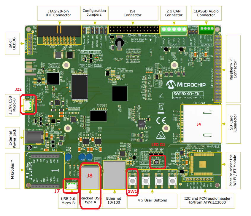
SAM9X60-EK Evaluation Board
- Setup the SD card (Note: exFAT formatted SD Cards are not supported)
- Download harmony MPU bootstrap loader from this location.
- Copy the downloaded boot loader binary (boot.bin) and generated application binary (harmony.bin) into the SD card.
- Insert the SD card into the SDMMC connector J4 on the board.
- Reset the board by pressing the Push Button SW3.
- Jumpers J20, J21, and J13 must be open.
- Jumper J2 and J3 must be shorted.
- Connect the External Power Jack (J1) to a 5V power supply.
- Connect 2 USB devices to the USB Host on the board:
- Stacked type-A USB (J8A)
- Stacked type-A USB (J8B)
-
LED D1 on the board indicates the file write is complete.

Note: Reset push button on SAM9X60 EK is labeled as SW3
SAM9X75-DDR3-EB Evaluation Board
- Powered the board with an external power supply (or use the micro AB connector).
- Setup the SD card (Note: exFAT formatted SD Cards are not supported)
- Download harmony MPU bootstrap loader from this location.
- Copy the downloaded boot loader binary (boot.bin) and generated application binary (harmony.bin) into the SD card.
- Insert the SD card into the SDMMC connector (SDMMC0) on the board.
- Reset the board by pressing the Push Button RESET, then START.
- Connect 2 USB devices to the USB Host on the board:
- Stacked type-A USB (J8A)
- Stacked type-A USB (J8B)
-
LED near VDDCORE inscription on the board indicates the file write is complete.

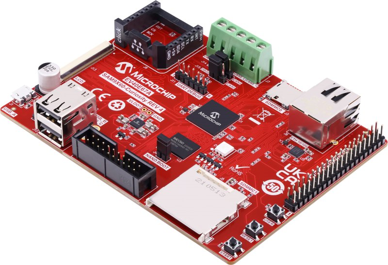
SAM9X60-Curiosity Board
- Setup the SD card (Note: exFAT formatted SD Cards are not supported)
- Download harmony MPU bootstrap loader from this location.
- Copy the downloaded boot loader binary (boot.bin) and generated application binary (harmony.bin) into the SD card.
- Insert the SD card into the SDMMC0 connector J3 on the board.
- Reset the board by pressing the Push Button RESET.
- Jumper J4 must be shorted.
- Connect the USB Micro-B Connector (J1) on the board to the computer using a micro USB cable.
- Connect 2 USB devices to the USB Host on the board:
- Stacked type-A USB (J10A)
- Stacked type-A USB (J10B)
-
LED D1 on the board indicates the file write is complete.

SAMA7G5-EK Evaluation Kit
- Powered the board with an external power supply (J1).
- Setup the SD card (Note: exFAT formatted SD Cards are not supported)
- Download harmony MPU bootstrap loader from this location.
- Copy the downloaded boot loader binary (boot.bin) and generated application binary (harmony.bin) into the SD card.
- Insert the SD card into the SD Card Connector (J4) on the board.
- Reset the board by pressing the Reset Button (nRST)
- Press the “nSTART” button to activate board start-up.
- Connect 2 USB devices to the USB Host on the board:
- Type-A connector USBC (J9)
- Type C Connector USBB (J8)
- Type micro A/B connector USBA (J7)
- RGB LED turning to Green indicates the file write is complete.
Running the Application
This application demonstrates the use of the MSD Host Class Driver to write a file to USB Flash drive. The application uses the USB Host_layer, MSD class driver and the MPLAB Harmony File System Framework to enumerate a USB Flash drive and to write a file to it.
- Open the project with appropriate IDE. Compile the project and program the target device.
- With the code running, attach a USB Flash drive to the Host connector on the desired starter kit containing a non empty file named file.txt
- Attach a second empty USB Flash drive to another Host connector on the desired starter kit
- The demonstration application will then copy the file.txt from the first USB Flash drive to the second.
- The LED on the selected hardware will indicate the status of the operation.
- The second USB Flash drive can then be attached to a USB Host personal computer to verify the demonstration application operation.
