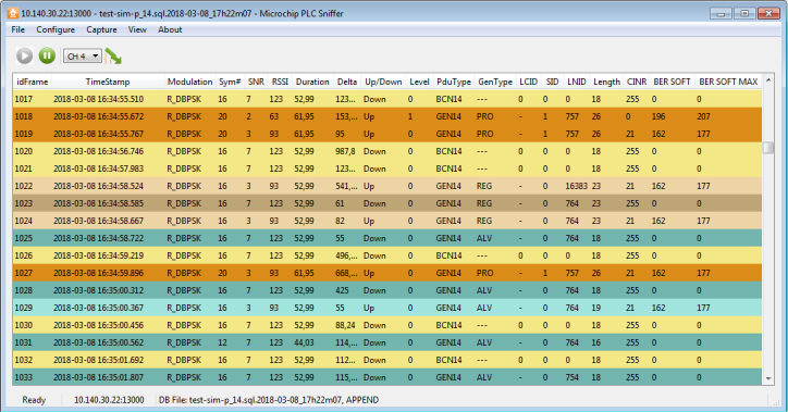
On a PRIME network, the main window will look like this:
The capture window has a tool bar with four commands:

Pause command will stop the update of the scroll view, while the logging process will continue. No frames will be lost. To restart showing the live stream of PDUs, click the play button.
Channel combo box allows selecting the PRIME channel to listen. A compatible device must be used; otherwise this option has no effect.
The last command button will set the CRC configuration on the hardware device. If enabled, the hardware device will calculate the CRC on all the frames, and discard frame errors. If disabled, all frames received will be sent to the PC software. The status of this setting is shown in the CRC column.
- idFrame: index of the frame
- Timestamp: timestamp of the frame. If it is not provided by the hardware/remote sniffer device, but added by the PC software. The timestamp is stored as a 64-bit integer, with resolution of milliseconds
- Modulation: modulation scheme used to transmit this frame
- Symbols: number of OFDM symbols used to transmit this frame
- SNR: signal-to-noise ratio as defined by PRIME standard, and returned by the “PHY_SNR.confirm primitive”
- ExSNR: extended SNR. SNR measured in dB
- RSSI: Received Signal Strength Indication, measured by the hardware sniffer in dBµV
- Channel: PRIME channel in which the sniffer is listening
- TimeIni: start of reception of this frame in reference to the first frame received. Units: milliseconds
- TimeEnd: end of frames. Unit: milliseconds
- Duration: length of this frame in milliseconds
- Delta: time between the beginning of this frame and the beginning of the previous frame
- CRC: shows if the CRC check is enabled on the hardware sniffer or performed by the software. If CRC is enabled on the hardware device, CRC value for the frame is not available
- UP_Down: Direction of the frame. Down means that a frame has its origin on the Base Node. Up frames originate in terminal nodes
- NAD: No aggregation at destination
- Level: indicates in which level on the topology the frame has been originated. A sniffer can listen frames from different levels in the hierarchy depending on the medium conditions
- PduType: defined by PRIME standard. PNPDU, BEACON, GENERIC
- GenType: defined by PRIME standard. Generic frames can be Control or Data PDUs
- LCID: Local Connection Identifier. Defined by PRIME Standard
- SID: Switch Identifier
- LNID: Local Node Identifier
- Length: Length of the PDU in bytes
- PrimeType: Frame type as defined by PRIME standard. It can be: Type A (PRIME 1.3 frames), Type B (Robust modes defined in PRIME 1.4 standard) or Type BC (Backwards Compatible frame, defined in PRIME 1.4 standard)
- RM: Robust mode, this field only makes sense in PRIME 1.4 networks. It specifies the weakest modulation a device can decode from a receiving peer
- TicksIni/TicksEnd: sniffer internal clock counter. This counter measures the time as seen by the source device. A 32-bit, 10 tenths of microsecond clock resolution. These values are used to compute the Duration and Delta values
- Hexa View
- Packet View
- Network View
- Nodes/Switches Plot
- Filter View