MCLV2 Development Board
Setting up the hardware
The following table shows the target hardware for the application projects.
| Project Name | Hardware |
|---|---|
| mclv2_sam_e54_pim.X | MCLV2 Development Board ATSAME54 Plug-in module Hurst Motor with encoder |
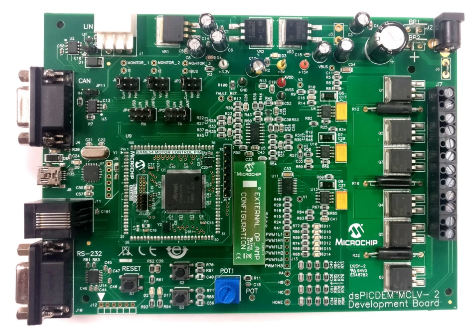
Setting up MCLV2 Development Board
-
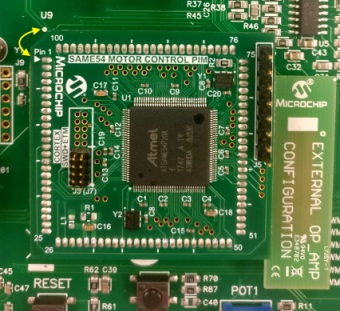
Mount the ATSAME54 Motor Control Plug In Module on U9 header.
-
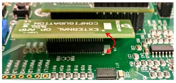
Place the “External Opamp Configuration” Matrix board at J14
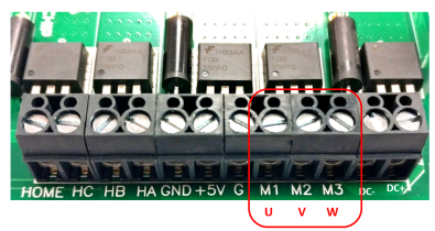
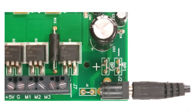
- Motor Connections:
- Phase U - M1 (White coloured wire)
- Phase V - M2 (Black coloured wire)
- Phase W - M3 (Red coloured wire)
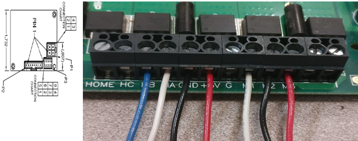
- Encoder Connections: Connect encoder wires as shown below
- 1 : +5V (Red coloured wire)
- 2 : HA (White coloured wire)
- 3 : HB (Blue coloured wire)
- 8 : GND (Black coloured wire)
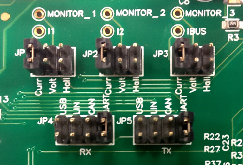
- Jumper Settings:
- JP1 - Curr, JP2 - Curr, JP3 - Curr
- In order to use RS232 port for X2CScope Communication JP4 - UART, JP5 - UART
- In order to use USB port for X2CScope Communication JP4 - USB, JP5 - USB
-
Power the board with a 24V DC supply using J2 or BP1-BP2. For additional safety, it is recommended to use a current limited power supply while testing this software demonstration on a non-default hardware and motor.
-
Complete Setup
Running the Application
- Build and Program the application using its IDE
- Press switch S2 to start the motor
- Vary potentiometer to change the reference rotor position of the motor
- Observe waveforms on X2CScope scope view
- Press the Switch S2 to stop the motor
Refer to the following tables for switch and LED details:
| Switch | Description |
|---|---|
| Switch S2 | To start or stop the motor |
| LED D17 Status | Description |
|---|---|
| OFF | No fault |
| ON | Fault is detected |