MCLV2 Development Board
Setting up the hardware
The following table shows the target hardware for the application projects.
| Project Name | Hardware |
|---|---|
| mclv2_pic32mk_mcf_pim.X | MCLV2 Development Board PIC32MK MCF Motor Plugin Module EBM-PAPST ECI 6320-K1-B00 motor |
Modify the MCLV2 Development Board
- Modify the MCLV2 development board for higher current capability- TC1 modifications. Refer the MCLV2 Development Board modification guide for more details.
Setting up MCLV2 Development Board
-
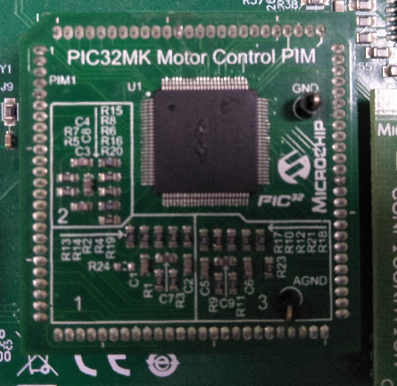
Mount the PIC32MK MCF Motor Control Plug In Module on U9 header.
-
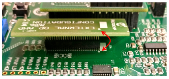
Place the “External Opamp Configuration” Matrix board at J14.
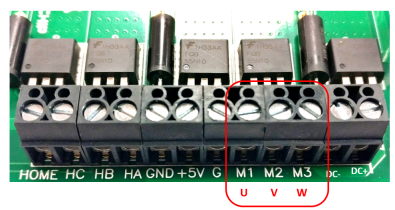
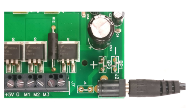
- Motor Connections:
- Phase U - M1
- Phase V - M2
- Phase W - M3
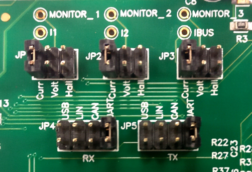
- Jumper Settings:
- JP1 - Curr, JP2 - Curr, JP3 - Curr
- In order to use RS232 port for X2CScope Communication JP4 - UART, JP5 - UART
- In order to use USB port for X2CScope Communication JP4 - USB, JP5 - USB
-
Power the board with a 24V DC supply using J2 or BP1-BP2. For additional safety, it is recommended to use a current limited power supply while testing this software demonstration on a non-default hardware and motor.
Running the Application
- Build and Program the application with
src/pic32mk_mcf_zsmt_firmware.hexusing Microchip’s IPE. - Press switch S2 to start the motor
- Vary potentiometer to change the speed of the motor
- Press switch S2 to stop the motor
- Press switch S2 again to start the motor
- Monitor graphs on X2C Scope
Refer to the following tables for switch and LED details:
| Switch | Description |
|---|---|
| Switch S2 | To start or stop the motor |
| LED D17 Status | Description |
|---|---|
| OFF | No fault |
| ON | Fault is detected |