MCHV3 Development Board
Setting up the hardware
The following table shows the target hardware for the application projects.
| Project Name | Hardware |
|---|---|
| mchv3_pic32cm_mc_pim.X | MCHV3 Development Board PIC32CM MC Motor Plugin Module ACIM Motor |
Note: For test purpose, Oriental Motor 4IK25A-SW2 motor has been used.
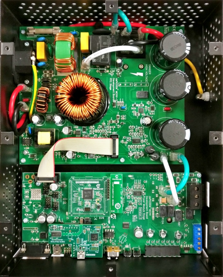
Setting up MCHV3 Development Board
-
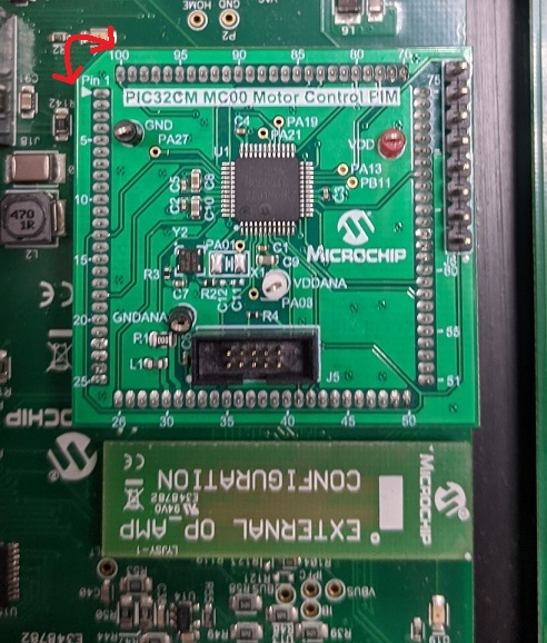
Mount the PIC32CM MC00 Motor Control Plug In Module on U11 header.
-
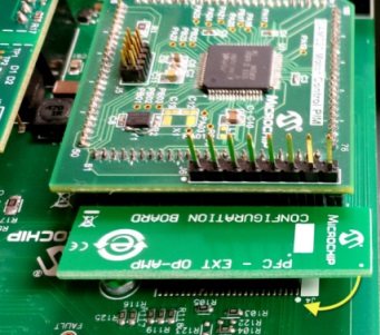
Place the “External Opamp Configuration” Matrix board at J4.
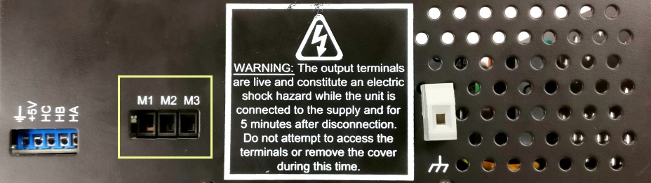
- Motor Connections:
- Phase U - M1
- Phase V - M2
- Phase W - M3
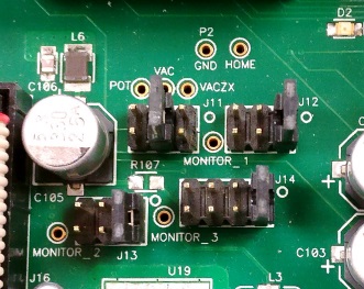
- Jumper Settings:
- J11 - VAC ( Short Pin 3 - 4)
- J12 - IA ( Short Pin 1 - 2)
- J13 - IB ( Short Pin 1 - 2)
- J14 - Fault_IP/IBUS ( Short Pin 1 - 2)
-
Power the board with (110V/220V) AC mains. For additional safety, it is recommended to use a current limited power supply while testing this software demonstration on a non-default hardware and motor.

-
Complete Setup
Running the Application
- Build and Program the application using its IDE
- Press switch PUSHBUTTON to start the motor
- Vary Potentiometer knob to increase the speed of the motor.
- Press switch to stop the motor
- Monitor graphs on X2C Scope
Refer to the following tables for switch and LED details:
| Switch | Description |
|---|---|
| PUSHBUTTON | To start or stop the motor |
| LED D2 Status | Description |
|---|---|
| OFF | No fault |
| ON | Fault is detected |