This application demonstrates a method of updating the maXTouch runtime configuration register set. It uses capabilities of the aria graphics library UI components and Harmony maxTouch driver API. It offers an easy to use menu interface to demonstrate the staging, loading, testing, and saving of configuration content. It accepts two file formats: maXTouch XCFG and RAW. The application employs USB/CDC serial, ProgramFlash, and SDCard source input. If offers a screen to select the load source, screen for touch testing, and capability to store configration to NVM non-volatile memory.
This demonstration contains sample maXTouch.raw and maXTouch.xcfg files. Use maXTouch Studio and support kits to create whole product configuration solutions which includes developing and debugging for all maXTouch devices.
The key points are:
- Capable of sourcing from PC USb serial streaming
- Capable of sourcing SDCard retrieval
- Capable of sourcing from ProgramFlash
- Non-volatile storage
- Supports XCFG and Raw file format

The aria_mxt_configuration application uses the aria graphics library to render graphics to the display. The graphics library draws the widgets and images to a frame buffer. The contents of the frame buffer are continuously transferred to refresh the contents of the LCD display. The application also features user touch input through the integrated touch screen on the display panel. Touch input from the touch controller goes through the I2C port, and the Input System Service acquires the touch input information from the Touch and I2C Drivers. Touch configuration uses the same I2C port as Touch input. Touch is disabled during configuration and re-enabled after completion. The Input System Service sends touch events to the Graphics Library, which processes these events and updates the frame data accordingly.
The block diagram(s) below show the various software and hardware blocks used in this application.
- Low-Cost Controllerless (LCC) Graphics driver on the SAM E70 device
- maXTouch file parsing, loading, and saving.
- USB/CDC serial, SYS_FS, Uart
- Button and Image Widgets
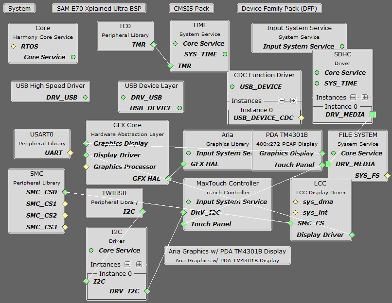
The Project Graph diagram shows the Harmony components that are included in this application. Lines between components are drawn to satisfy components that depend on a capability that another component provides.
Adding the “SAM E70 XPlained Ultra BSP”and the “Aria Graphics w/ PDA TMA4301B Display” components into the project graph will automatically add the components needed for a graphics project and resolve their dependencies. It will also configure the pins needed to drive the external peripherals like the display and the touch controller.
In this configuration, a 16-bit RGB565 frame buffer is stored in internal SRAM. Due to the limited size of the internal SRAM, only a single frame buffer can be used which can cause tearing to be visible as the GFX library draws on the screen. These configurations use the Low-Cost Controller-less (LCC) display driver to manage the DMA that transfers the framebuffer contents to the display.
The parent directory for this application is gfx_apps/apps/aria_mxt_configure. To build this application, use MPLABX to open the gfx_apps/apps/aria_mxt_configure/firmware/aria_mc_e70_xu_tm4301b.X project.
The following table lists configuration properties:
|
Project Name |
BSP Used |
Graphics Template Used |
Description |
|
aria_mc_e70_xu_tm4301b.X |
sam_e70_xmplained_ultra |
Aria Graphics w/PDA TM4301B Display |
SAM E70 Xplained Ultra board with PDA TM4301B 480x272 (WQVGA) Display |
 Important! Important! |
This application may contain custom code that is marked by the comments // START OF CUSTOM CODE ... and // END OF CUSTOM CODE. If you use the MPLAB Harmony Configurator to regenerate the application code, use the "ALL" merging strategy and do not remove or replace the custom code. |
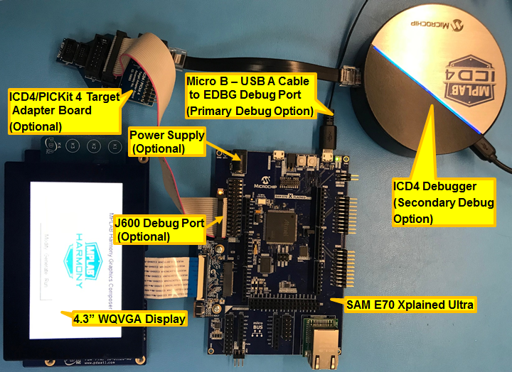
There are two programming options. The primary option is the Micro B Embedded Debugger (EDBG) port. Power to the board can also be supplied via this connection. The secondary option is via the ICD4 debugger with the ICD4/PICKit 4 Target Adapter Board (Power has to be provided from power supply in this alternative setup).
The image below shows both the EDBG and the ICD4 connection options:
Configuring the 4.3” WQVGA Display requires disconnecting the ribbon cable that connects the display to the interposer board.

First, release the ribbon cable from the interposer board. Next, release the black clamp on the E70’s J2 connector and turn the display over. Finally, insert the ribbon cable into J2 and close the clamp.

The board and display are powered by a Micro B – USB A cable from PC to the “Debug USB” port on the E70 board. The ICD4 Debugger and ICD4/PICKit4 Adapter Board are connected as shown above.
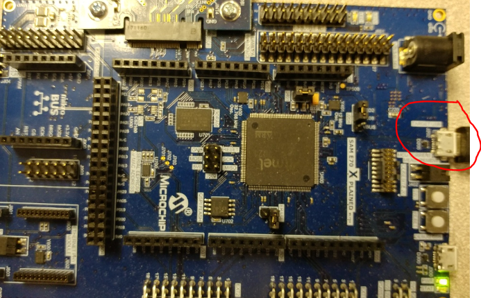
Note: For PC file transfer, insert Micro B – USB A cable from PC to the “Target USB” port on the E70 board.
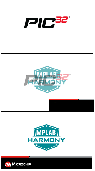
Upon boot-up, the application displays the animation Splash Screen, which shows an animated splash bar while blending in the MPLAB Harmony and Microchip PIC32 logos, as shown in the following figure.
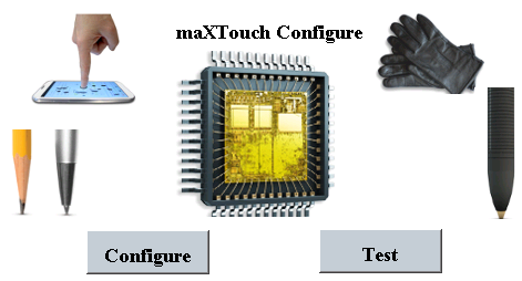
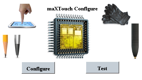
When Splash Screen animation is successful, the demonstration will display a similar menu to that shown in the following figure.
When power-on is successful, the application Home Screen will be displayed
The demonstration supports three input options for reading the configuration file:
- Program Flash - ProgramFlash is the default option and requires no manual source file interaction. The maxtouch config data is save in program flash as an array.
- SDCard - requires a microSDHC flash memory card. Copy maxtouch.raw onto root directory of memory card. Install memory card into micro SD card slot.
- Host PC - requires a micro-usb cable connection from PC to Target USB port. For this option install RealTerm: Serial/TCP Terminal program.
Note: This demonstration does not communicate error conditions related to inability to read from SDCARD or PC.
Following instructions below for each specific option of choice:
This is the default option. The config content is embedded in program flash of the firmware. This option requires no external file preparation.
To run this option.:
- On the Main Menu, press the Configure button. The application will transition to the Load Configuration (RAM) screen.

- On the Load Configuration Screen, select Program radio button. This will enable configuration reading from Program Flash.
- Press the Load button. The step will read, parse, and load the configuration information located in Program Flash.
- Observe the target board UI progress bar.
- When complete, the Load button will be removed, and the Next
 ) screen button image will be displayed.
- Go to Step "All Options" below.
This option requires a SDCARD. The SDCARD should be loaded with maxtouch.xcfg or maxtouch.raw file in the root folder. Only 1 file can be store on the SDCARD for this release. An example maxtouch.xcfg file can be found at the following location: <installdir>/apps/gfx_apps/aria_mxt_configure /firmware/src/config_files
To run this option.
- On the Main Menu Press the Configure Button. The application will transition to the Load Configuration screen.
- On the Load Configuration Screen, select SD Card radio button. This will enable the reading from the microSD card inserted in the SD Card slot.
- Press the Load button. The step will read, parse, and load the configuration information located in the maxtouch.xcfg or maxtouch.raw file.
- Observe the target board UI progress bar. When complete, the Load button will be removed, and the Next () screen button image will be displayed.
- Go to Step "All Options" below.
This option requires a HOST PC connected to the Target board. The configuration file will be streamed from the Host PC to the Target board. For the purpose of this option, the user should establish a host PC connected to the Target board via a USB cable. A USB cable needs to be connected to the micro-B USB connector on the bottom of the starter kit in use. When the demonstration runs, it will create a USB CDC device on the USB bus. The demonstration can be executed once you have connected to this device through RealTerm terminal program. See the following download link: RealTerm
Please refer to the connection diagram shown below.
To run this option.:
- On the Main Menu Press the Configure Button. The application will transition to the Load Configuration screen.
- On the Load Configuration Screen, select PC radio button. This will enable the reading from Host PC.
- Press the Load button. The step will create the USB CDC device on the USB bus, establish connection, and wait for PC to initiate the transfer.
- On the PC, invoke RealTerm application .
- Using the Port Tab, connect to the new Serial comm port.
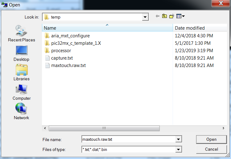
- Using the Send Tab, select the Dump File to Port drop down. Select the maxtouch.raw file.
- Set Delays to 1 and 5
See image below for Realterm Send setup:
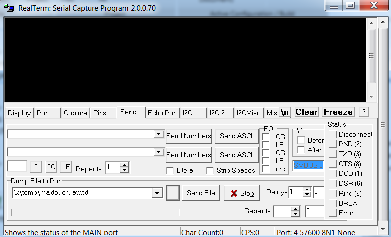
- Finally, select the Send File button
- When complete, the Progress bar on the RealTerm interface will display “Done”
See image below for Realterm Done display:

- Observe the Target board UI , when complete, the Load button will be removed, and the Next () screen button image will be displayed.
- Go to Step "All Options" below.
To complete the demonstration for all options.
- Use the Next {} button to transition to the Key Pad Touch Accuracy test screen.
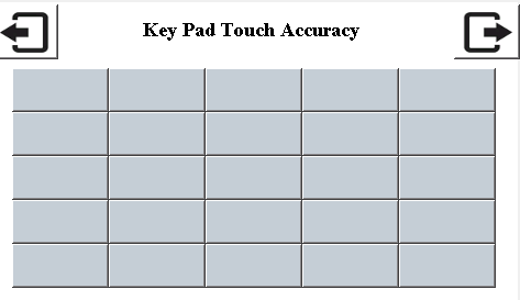
- Press key pad buttons to test touch button accuracy.
- Use Next to transition to the Multi Touch Test Screen
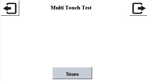
- Drag finger across display, to test gesture accuracy.
- Use Next button Button to transition to the Store Configuration (Flash) Screen
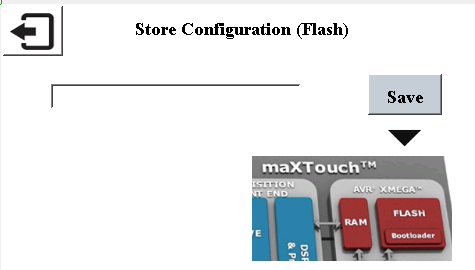
- Press Save button to copy config information from maXTouch RAM to maXTouch non-volatile memory for persistent storage.
|
MPLAB® Harmony Graphics Suite Applications
|