The project uses a draw surface widget as a container to draw the gauge needle using lines. When the user touches the screen, a touch event is sent to the application. The application updates the values of the tachometer, speedometer and fuel gauge. The needle is cleared and redrawn every time the tachometer value changes. The speed, distance and fuel gauge are also updated. Label widgets are used to show the speed and distance, while image widgets are used to show the indicators and fuel gauge.
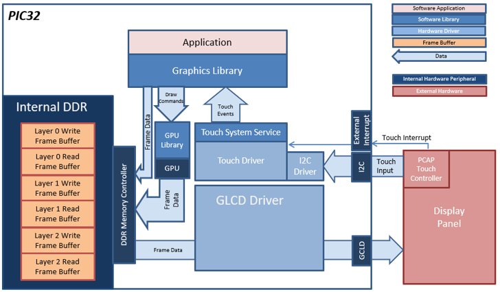
The application uses the 3 layers in the LCDC display controller to compose the final screen. Each layer uses double-buffering to eliminate tearing. When the screen needs to be updated, the graphics library updates the frame on the write buffer while the LCDC display controller sends the read buffer content to the display panel. When the graphics library is done updating, the write buffer is swapped with the read buffer and its contents are pushed out to the display controller.
Each frame buffer uses 32-bit per pixel, and each pixel has its own alpha channel. This allows the sections of the upper layers to be transparent and show the contents of the layers underneath.
User touch input on the display panel is received thru the PCAP capacitive touch controller, which sends a notification to the Touch Input Driver. The Touch Input Driver reads the touch information over I2C and sends the touch event to the Graphics Library thru the Input System Service.
Demonstration Features
• GLCD display controller with multiple HW layers
• Nano2D Graphics Processor Unit (GPU)
• Input system service and driver
• Time system service, timer-counter peripheral library and driver
• I2C driver
• 32-bit RGBA8888 color depth support
• Draw surface, image, label widgets
• Software-based image rotation
• Backlight PWM control
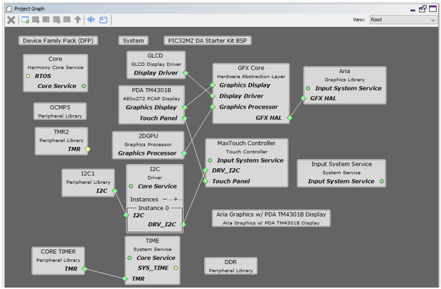
The Project Graph diagram shows the Harmony components that are included in this application. Lines between components are drawn to satisfy components that depend on a capability that another component provides.
First, add the “PIC32MZ DA Starter Kit BSP” into the project. Then, add “Aria Graphics w/ PDA TM4301B Display” Graphics Template component to the project if using a 4.3” WQVGA TM4301b display or the “Aria Graphics w/ PDA TM4301B Display” Graphics Template component to the project if using a 5” or 7” WVGA TM4301b display. The template will automatically add the components needed for a graphics project and resolve their dependencies and configure the pins needed to drive the external peripherals like the display and the touch controller.
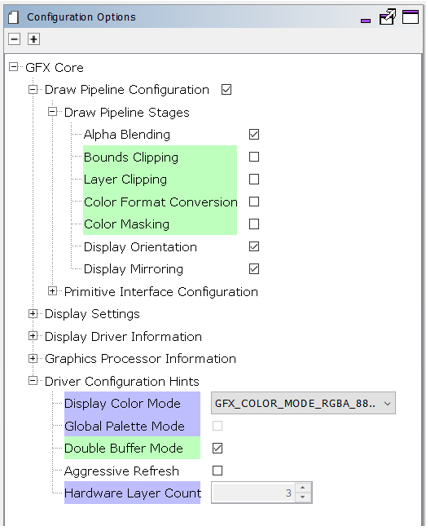
For this project, the GFX Core component has been configured to enable “Double Buffer Mode” for double-buffering.
The GFX template automatically sets the heap size to 32768 bytes. The heap is set in the System component properties as shown in the image below.
The parent directory for this application is gfx/apps/aria_dashboard. To build this application, use MPLABX to open the gfx/apps/aria_dashboard/firmware/aria_db_mzda_intddr_sk_meb2_tm4301b.X project file.
The following table lists configuration properties:
|
Project Name |
BSP Used |
Graphics Template Used |
Description |
|
aria_db_mzda_intddr_sk_meb2_tm4301b.X |
PIC32MZ DA Starter Kit |
Aria Graphics w/ PDA TM4301b Display |
Aria GFX on PIC32MZ DA with Internal DDR Starter Kit, MEBII and PDA TM4301b Display |
Note: This application may contain custom code that is marked by the comments "// START OF CUSTOM CODE ..." and "// END OF CUSTOM CODE". If you use the MPLAB Harmony Configurator to regenerate the application code, do not remove or replace the custom code.
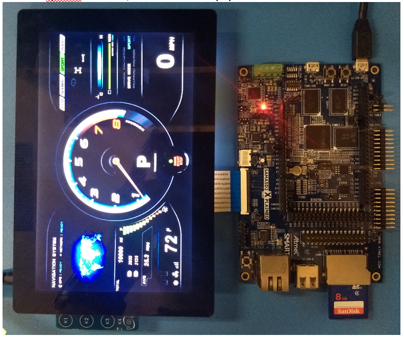
The final hardware set-up should be:
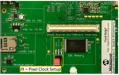
On the MEB II, the EBIOE and LCD_PCLK (J9) must be jumpered. A connection establishes the GLCD's pixel clock output timing. The external SRAM memory on the board is disabled. The J9 jumper is located on the bottom of the MEB II board, beneath where the starter kit is plugged into the board. Refer to the following figure for the exact location.
Connect the PIC32MZ DA Starter Kit to the MEB II board

Power up the board by connecting the power adapter to J3 power connector on the MEB II board or a powered USB cable to the USB DEBUG port on the Starter Kit board.
The final hardware setup should be:
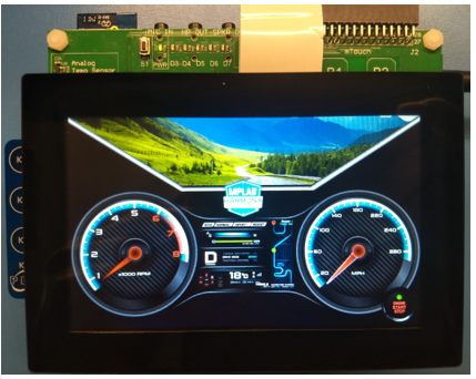
PIC32MZ DA Starter Kit with MEBII and 5” WVGA PCAP Touch Display
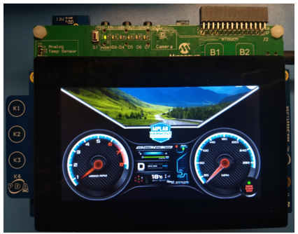
PIC32MZ DA Starter Kit with MEBII and 4.3” WQVGA PCAP Touch Display
On start-up, the application will display a splash screen. After the splash screen completes, the dashboard screen is shown. The initial state of the dashboard screen is “OFF” where the backlight is slightly dimmed, the needle in the 0 RPM position and the indicators and labels are hidden. Pressing the “ENGINE START STOP” button at the center-bottom section of the screen will “TURN ON” the dashboard.
As the dashboard is turning on, the indicators and labels will show up, the tachometer needle will turn to MAX and back and the fuel gauge bars will go to full.
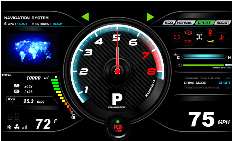
Touching the screen will simulate a running vehicle, and the tachometer gauge needle, speed and distance labels, fuel gauge will change. Touching the left or right side of the screen will toggle the left or right-turn indicators. When the fuel gauge goes down to empty (“E”), the simulated vehicle will go to a stop and refuel.
Touching the “ENGINE START STOP” button will “TURN OFF” the dashboard where the backlight will be dimmed and the indicators/labels will be hidden.
|
MPLAB® Harmony Graphics Suite Applications
|